Chapter 5 Feature Reference
5-6 Making Various Adjustments for Cutting
121
Chapter 5 Feature Reference
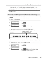
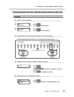
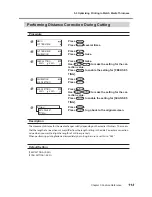
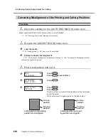
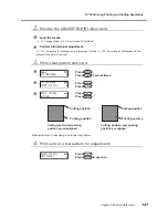
4.
Print and cut a test pattern for setting the correction values.
Press
.
Press
to execute
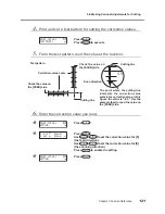
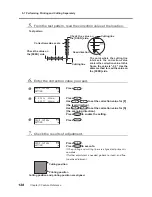
5.
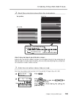
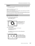
From the test pattern, read the value at the location.
6.
Enter the correction value you read.
Press
.
Press
.
Use
to set the correction value for [F]
(the feed direction).
Use
to set the correction value for [S]
(the scanning direction).
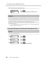
Press
to enable the setting.
Press
.
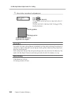
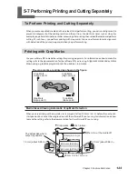
PRINT - CUT ADJ.
TEST PRINT 2
PRINT - CUT ADJ.
SETTING
F :- 0.30 - 0.30mm
S : 0.00 - 0.20mm
PRINT - CUT ADJ.
SETTING
Test pattern
Check the value on
the [SCAN] side.
Correction-value scale
Check the value on
the [FEED] side.
Cutting line
Scan direction
The point where the cutting line
intersects the correction-value
scale is the correction value. In this
figure, the value is "-0.3." Use the
same method to read the value on
the [FEED] side.
Cutting line
Содержание LEC-300A
Страница 24: ...22 ...
Страница 25: ...Chapter 1 Introduction 23 ...
Страница 32: ...30 ...
Страница 33: ...Chapter 2 Basic Operation 31 ...
Страница 56: ...54 ...
Страница 57: ...Chapter 3 Operation of the Me dia Take up System 55 ...
Страница 65: ...Chapter 4 Maintenance and Adjustment 63 ...
Страница 91: ...Chapter 5 Feature Reference 89 ...
Страница 151: ...Chapter 6 What to Do If 149 ...
Страница 164: ...162 ...
Страница 165: ...Chapter 7 Specifications 163 ...
Страница 173: ...171 ...
Страница 174: ...172 ...
Страница 175: ...173 ...
Страница 176: ...174 ...
Страница 177: ...175 ...
Страница 178: ...176 ...
Страница 179: ......
Страница 180: ...R1 091026 ...

