11
OPERATION
(continued)
HIGH-ALTITUDE OPERATION:
Due to a decrease in atmospheric pressure air compressor pumps produce less CFM at higher elevations. As a rule of
thumb the output will decrease approximately three percent per 1000 feet of elevation. Also, because air at higher elevations is less dense and
does not cool as well, electric motors cannot be subjected to the full nameplate service factor amp rating and may need to be upgraded to avoid
repeated overheating.
Direct drive or hand-carry compressors built with cold-start valves may need to be modified when operated in higher elevations.
Carburetors on gas-powered air compressors may also need to be rejetted to perform properly at higher elevations. Contact our factory Customer
Service Department if your normally reliable air compressor fails to operate correctly at higher elevations.
INFREQUENT USE/CONDENSATION/MILKY OIL:
As the pump warms up moisture in the air inside the crankcase may condense into liquid form on
the cold internal parts. If the pump is not allowed to reach full operating temperature for a reasonable amount of time the moisture may never
evaporate and could get mixed into the oil to produce a milky white sludge. Over time the internal moisture created due to infrequent use could
lead to premature pump failure.
You may be able to prevent moisture from forming inside the pump by increasing ventilation around the air compressor, operating for
longer intervals, decreasing humidity levels, or installing a crankcase heater kit. Crankcase heaters are also recommended when operating in
ambient temperatures consistently below 40°F. Please contact our customer service department if your air compressor pump continually develops
milky oil.
DUTY CYCLE:
All ROLAIR belt-driven air compressors are equipped with S1 or 100% duty cycle motors and pumps. Given proper ventilation and
electrical power, your ROLAIR compressor is capable of operating continuously when set up for constant speed operation. However, an excessive
amount of starts per hour may generate enough heat to trip the motor overload. Please contact our factory Customer Service Department if
overload problems repeatedly occur.
SYSTEM COMPONENTS
To prevent overheating and burn-out due to an overload or low voltage, any motor not already equipped with thermal overload
protection and a manual reset button must always be protected by a properly sized starter. Failure to install the proper starter and overloads will
void the motor manufacturer’s warranty. Follow the National Electric Code or local electric code in providing wiring, fusing and disconnect
switches.
E
fficiency and safety are the primary concerns when selecting components for compressed air systems. Products of inferior quality can
not only hinder the performance of the unit, but could cause system failures or bodily harm. Select only top quality components for your system.
Call your local ROLAIR distributor for quality parts and professional advice.
DRIVE PULLEYS:
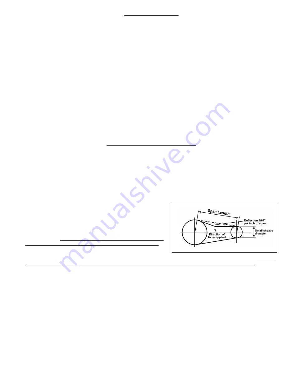
Drive pulleys must be properly aligned and drive-belt tension set to
specifications. Improper pulley alignment and belt tension can cause motor
overloading, excessive vibration and premature belt and/or bearing failure.
GUARDS:
All mechanical action or motion is hazardous in varying degrees and
needs to be guarded. Guards should be designed to achieve the required degree of
protection and still allow full air flow from the compressor flywheel across the unit.
Guards shall be in compliance with O.S.H.A. safety and health standards and any
state or local codes. When the compressor is installed, make sure guard side is at
least 18” away from the wall to provide adequate cooling of motor and pump.
CHECK VALVES:
Check valves are designed to prevent back-flow of air pressure in
the compressed air system (air flows freely in one direction only.) The check valve must be properly sized for air flow and temperature. Do not rely
upon a check valve to isolate a compressor from a pressurized tank or compressed air delivery system during maintenance procedures!
MANUAL SHUT-OFF VALVES:
Manual shut-off valves block the flow of air pressure in either direction. This type of valve can be used to isolate a
compressor from a pressurized system, provided the system is equipped with a safety-relief valve capable of being manually released. The safety-
relief valve should be installed between the manual shut-off valve and the compressor.
SAFETY-RELIEF VALVES:
Safety-relief valves aid in preventing system failures by relieving system pressure when compressed air reaches a
determined level. A check valve and safety relief valve are required in all compressed air systems. Safety-relief valves are pre-set by the
manufacturer and under no circumstances should the setting be changed.
PRESSURE SWITCHES:
The pressure switch detects the demand for compressed air and allows the motor to start. When the demand is satisfied,
the unit stops and unloads the head pressure with a short hissing noise. Engine-driven units use a pilot valve instead of a pressure switch. It will
discharge compressed air to atmosphere or open the intake valve upon reaching a predetermined pressure setting.
PRESSURE VESSELS:
ASME coded pressure vessels must not be modified, welded, repaired, reworked or subjected to operating conditions outside
the nameplate ratings. Such actions will negate code status.
DRIVE PULLEY


