background image

Version 4.00 / 07-2004

Operating Manual

Power Supply NGMO1
and
Power Supply NGMO2

192.1500.21 and 192.1500.24

Содержание NGMO1

Страница 1: ...Version 4 00 07 2004 Operating Manual Power Supply NGMO1 and Power Supply NGMO2 192 1500 21 and 192 1500 24 ...

Страница 2: ... permission from ROHDE SCHWARZ GmbH Co KG Disclosure or reproduction of this documentation utilization and communication of its contents is not permitted without express approval Infringements will lead to claims for compensation All rights reserved in the event of patents being granted or registration of a protected design ROHDE SCHWARZ GmbH Co KG Mühldorfstraße 15 D 81671 München Phone 49 0 1805...

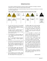
Страница 3: ...of the unit should only be performed by qualified tech nical personnel 4 For permanently installed units without built in fuses circuit breakers or similar protective de vices the supply circuit must be fused such as to provide suitable protection for the users and equipment 5 Prior to switching on the unit it must be ensured that the nominal voltage set on the unit matches the nominal voltage of ...

Страница 4: ...thium batteries must not be exposed to high temperatures or fire Keep batteries away from children If the battery is replaced improperly there is danger of explosion Only replace the battery by R S type see spare part list Lithium batteries are suitable for environmentally friendly disposal or specialized recycling Dis pose of them in appropriate containers only Do not short circuit the battery 12...

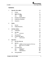
Страница 5: ...Safety Instructions 2 1 3 Unit Description 3 1 3 1 Introduction 3 1 3 2 Overview 3 2 3 2 1 Accessories 3 3 3 3 Specifications 3 4 3 4 Function Description 3 7 3 4 1 Communication 3 7 4 Operation 4 1 4 1 Operation Elements 4 1 4 2 Start Up 4 5 4 2 1 NGMO2 Line Power Connection and Power up 4 5 4 2 2 Main Functions of the NGMO2 4 5 4 2 3 Menu 4 9 4 3 Test Connections 4 20 4 3 1 Remote Sense 4 20 4 3...

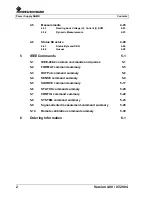
Страница 6: ...ues 4 28 5 IEEE Commands 5 1 5 1 IEEE 488 2 common commands and queries 5 1 5 2 FORMAT command summary 5 5 5 3 OUTPut command summary 5 6 5 4 SENSE command summary 5 9 5 5 SOURCE command summary 5 17 5 6 STATUS command summary 5 20 5 7 CONFIG command summary 5 22 5 8 SYSTEM command summary 5 23 5 9 Signal oriented measurement command summary 5 28 5 10 Remote calibration command summary 5 30 6 Orde...

Страница 7: ...3 4 Circuit diagram Mobile phone connected to the NGMO2 3 8 Fig 4 1 NGMO2 Operation elements on the control panel 4 1 Fig 4 2 Four wire sense connection 4 20 Fig 4 3 Local sense connections 4 21 Fig 4 4 Sample values 4 24 Fig 4 5 Pre trigger and post trigger acquisition 4 25 Fig 4 6 Measurement repetition 4 26 Fig 4 7 Status model structure 4 29 ...

Страница 8: ...Power Supply NGMO Tables 4 Version 4 00 07 2004 ...

Страница 9: ...ontains descriptions for all versions In chapters with differences in the description of the individual Power Supplies such differences will be specially emphasized The designation NGMO is used wherever the description applies for all versions If you use this manual for a NGMO1 Just ignore all descriptions and specifications which belong to the channel B of the power supply This is also valid for ...

Страница 10: ...O This manual describes safe installation and assembly appropriate and safe operation of the Power Supply Read the operating instructions carefully before you use the Power Supply The operating instructions contain important information which must be acted on Apart from the information in the operating instructions the statutory safety regulations that apply in the country of use the relevant tech...

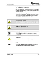
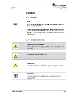
Страница 11: ...f safety for personnel working with the Power Supply NGMO safety regulations must be observed Certain sections of the text are highlighted as follows ELECTROCUTION HAZARDS Observe the relevant safety regulations when operating electri cal devices Observe the operating instruction WARNING Failure to follow the instructions could damage the Power Supply NGMO ATTENTION Failure to follow the instructi...

Страница 12: ...nit from the ship ping carton check for any obvious signs of physical damage that may have occured in transit Remove any protective film over the screen Report any damage to the shipping agent immediately Save the origi nal packing carton for any future shipments The following items are included with every order 1 Power Supply NGMO 1 power cable 2 output connectors 1 Operating manual ...

Страница 13: ...SCHWARZ GmbH Co KG will not assume liability for any resulting damage and all warranties will become null and void 2 2 Safety Instructions ELECTROCUTION HAZARDS Observe the relevant safety regulations when operating electri cal devices Observe the operating instruction ATTENTION Failure to follow the instructions may cause spurious results WARNING Failure to follow the instructions could damage th...

Страница 14: ...Power Supply NGMO Safety 2 2 4 00 07 2004 ...

Страница 15: ...annels NGMO2 only NGMO1 only Channel A which can be used as the following high speed voltage source programmable DC load precise digital multimeter sampling oscilloscope This unit fulfils all requirements of latest electronic battery powered communication products The high speed and the high reliability are features which are very im portant in a production environment The NGMO is an ideal device ...

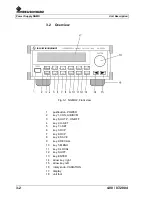
Страница 16: ... view 1 pushbutton POWER 2 key 1 CHN A B DVM 3 key 6 OUTP ON OFF 4 key 2 U SET 5 key 7 I SET 6 key 3 OVP 7 key 8 OCP 8 key 4 SAVE 9 key 9 RECALL 10 key 5 MENU 11 key 0 LOCAL 12 key SHIFT 13 key ENTER 14 arrow key right 15 arrow key left 16 rotary knob VARIATION 17 display 18 unit foot ...

Страница 17: ...3 3 Fig 3 2 NGMO2 Rear view 1 Channel A Connector 2 Channel B Connector 3 Mains 120 230 VAC 4 Voltage Selector 5 IEEE488 2 Connector 6 RS485 232 Connector 7 Control I O Connector 3 2 1 Accessories 1 power cable 2 output connectors 1 operating manual ...

Страница 18: ...t connected 35 µs 35 µs at long leads sensed 50 µs 50 µs with narrow bandwidth direct connected 80 µs 80 µs at long leads sensed 100 µs 100 µs Transient voltage drop on load change 0 1 A to 1 6 A with wide bandwidth at long leads sensed 60 mV 60 mV ripple and noise 1 mVRMS 1 mVRMS output impedance 0 to 1 Ω settable in 10 mΩ steps 0 to 1 Ω settable in 10 mΩ steps voltage compensation up to 1 V 4 V ...

Страница 19: ... Current measurement Ranges 7 A 0 5 A 5 mA 7 A 0 5 A 5 mA resolution 200 µA 10 µA 0 1 µA 200 µA 10 µA 0 1 µA deviation from full scale 15 mA 1 mA 10 µA 5 mA 1 mA 10 µA Measurement time 2 ms to 200 ms settable 2 ms to 200 ms settable averaging 1 to 10 values 1 to 10 values Dynamic measurement Sample buffer 1 to 5000 points 1 to 5000 points Sample time 10 µs to 1 s in 10 µs steps 10 µs to 1 s in 10 ...

Страница 20: ...EEE488 2 RS232C Control inputs 2 x measurement trigger 2 x output inhibit Control outputs 2 x complete 4 x relay driver fault AC supply 110 115 V and 220 230 V selectable 50 to 60 Hz AC input power 220 VA max 220 VA max Dimensions 210 8 mm x 87 6 mm x 420 mm without rear and buttom feet Mass 7 5 kg Environmental Data Humidity 85 at 35 C non condensing Operating temperature range 0 to 45 C Nominal ...

Страница 21: ...4 FORCE 4 RELOUT 4 output relay driver open collector 28 VDC 200 mA 5 SENSE 5 FAULT output fault signal open collector 28 VDC 200 mA 6 SENSE 6 NC not used not used 7 FORCE 7 NC not used not used 8 FORCE 8 GND GND signal GND 9 GND GND signal GND 10 INHIBIT_B input external inhibit signal TTL 0 12 VDC 11 TRIGGER_B input external inhibit signal TTL 0 12 VDC 12 INHIBIT_A input external inhibit signal ...

Страница 22: ...nts internal and external triggers for current and voltage measurements separate DVM s DC load capability up to 2 8 A high voltage setting resolution precise low current measurements very low ripple and noise settable output impedance for battery emulation OVP OCP open sense detection auxiliary inputs outputs output inhibit relay complete small dimensions 2 HU half 19 interfaces IEEE488 2 RS232 an...

Страница 23: ...he Power Supply NGMO2 NOTE Operation elements and Start up functions of the Power Supply NGMO1 are identical with the NGMO2 Operation elements for channel B must in this case be ignored Readings in the LC Display correspond with the respective Power Supply Fig 4 1 Power Supply NGMO2 Operation elements on the control panel ...

Страница 24: ...NNEL B 1 Digital Voltmeter A Digital Voltmeter B By pressing this key channel A or channel B and the associated DVM can be selected The selected DVM shows an applied external voltage key 2 Voltage setting Press U SET to set the output voltage you have selected The value you want and if necessary modified by pressing the SHIFT key or by turning the variation knob key 3 Overvoltage protection By pre...

Страница 25: ...tput is limited to max 2 5 A key 8 Overcurrent protection Pressing this key allows you to choose between the options current protection mode or current limit mode When the current protection mode has been selected the output is switched off when the max output current exceeds the set current limit key 9 RECALL The RECALL key is used to recall all settings stored in memory locations 1 to 9 Memory l...

Страница 26: ...the control panel CHN 1 A B DVM to 0 LOCAL and SHIFT are assigned two functions e g apart from the main setting functions the numerals 0 to 9 and the decimal point printed on the keys can be entered to alter values when the shift key has been pressed UUT stands for unit under test in the sequel ...

Страница 27: ...e POWER switch has not been pressed and shows OFF 2 Check that the Mains Voltage Selector 4 Fig 5 2 is set to the appropiate line voltage 3 Connect the female end of the power cable to the AC receptacle on the rear panel 4 Connect the Power Supply NGMO to the AC line 5 Press the push button Power on the front panel 4 2 2 Main Functions of the NGMO When the NGMO2 is powered up it displays the follo...

Страница 28: ... of power supply A is currently turned on AB OFF is displayed if function A B24 Common output on off see below Menu Items is turned on and both outputs are off AB ON is displayed if function A B24 Common output on off see below Menu Items is turned on and both outputs are on PROT is displayed if the OCP key has been pressed so activating the overcurrent protection function In OCP active mode the o...

Страница 29: ...at currently the DVM measurement input of chan nel A has been selected The value of the voltage applied to chan nel A DVM input is currently displayed z zzz is the value of the measured voltage in volts DVMA is selected by pressing the CHN key line 2 is similar to example 1 line 2 Example 4 is similar to example 3 except that the voltage of DVM input of channel B is displayed DVMB can also be sele...

Страница 30: ...its left of the cursor are increased Turning the knob counter clockwise decreases the value To exit the entry mode press either the ENTER key or the function key The underscore cursor then disappears 4 2 3 2 How to Enter a Numerical Value directly To enter a numerical value directly you must also first select a function that accepts a numerical input by pressing e g U SET I SET and OVP After that ...

Страница 31: ...nob The action to chan ge an item value or setting depends on the kind of item If an item type has predefined options just press the left arrow key to move the square brackets around a value one to the left and the right arrow key to move it one to the right The new selected setting comes into effect immedi ately The ENTER key does not need to be pressed Items that accept numerical values are chan...

Страница 32: ... value from 2 to 200 ms can be selected A B03 Static Measure Average Count 1 10 This setting specifies the average count for static current and DVM measurements Values from 1 to 10 can be selected The total measurement time for static measure ments is the product of Static Measure Interval multiplied by Static Measure Average Count A B04 Output Impedance 0 1 00 Ohms This menu item lets you set the...

Страница 33: ...r level in the 0 5A range see menu item A B01 and the signal analysis functions Any value between 0 00 mA Auto and 500 00 mA that is multiple of 10 uA can be selected An asterisk on the right of line two of the LCD indicates when 0 5A range has been selected in menu item A B01 A B09 Trigger Level DVM 6 000 25 000V Lets you set the trigger level for the DVM input see menu item A B06 and the signal ...

Страница 34: ...ifies a high to low transition A B13 Trigger Count 1 100 The trigger count specifies the number of times the analysis measurement is repeated to calculate the average value for Average Peak Min High Low and RMS functions Any value from 1 to 100 can be selected A B14 Trigger Offset 5000 50000 points The trigger offset specifies a trigger delay for analysis measurements in terms of a certain number ...

Страница 35: ...ycle is repeated is given by the Trigger count see A B13 If Trigger timeout see A B10 is set to a value greater than 0 and no trigger condition is met after Sampling start is set to ON for the time specified by Trigger timeout the error message Trigger timeout is displayed on the LCD Both conditions a normal end of measurement or a Trigger timeout will reset the Sample start to OFF A B18 Read SAMP...

Страница 36: ... A B22 Maximum output Current 0 000 5 000 A This menu item is an NGMO2 safety feature Setting a current value below 5 000 Amperes limits the maximum settable output current limit in the main display to the current limit given here A connected device is therefore protected from currents above the maximum allowed ratings A B23 Beep on Current limit on off When Beep on Current limit is set on the NGM...

Страница 37: ...8 Relay 4 on off Turns the output driver for relay 4 on or off The driver signal is applied to the Control I O connector Pin 4 on the rear panel ground on pin 8 and 9 A B29 Recall setting when power on 0 10 The NGMO2 saves sets of settings in an internal EEPROM With the menu item Recall settings when power on a user can select which of the stored settings are loaded when the device is powered up 0...

Страница 38: ...ial count of Databits 7 8 This menu item selects the data length for the serial interface This can be either 7 bits or 8 bits Note when a data length of 7 is selected only even or odd parity can be used due hardware limitations of the internal interface This setting is independent of the setting made with menu item 29 recall setting when power on A B34 Serial Parity node odd even With menu item Se...

Страница 39: ...mes that both ends are always ready for data transfers HW NGMO2 uses the serial handshake lines RTS and CTS for handshaking If RTS is low not active no data must be sent to NGMO2 If CTS is low no data is send from NGMO2 Xon XOff NGMO2 uses a software handshake for serial communication The Xoff control character suspends serial communication XON continues serial communication A B37 Serial Receive D...

Страница 40: ...ion mode Press ENT to select After pressing the enter key the user enters the calibration mode for the NGMO See Service Manual Chapter 7 192 1500 82 NOTE The calibration of the Power Supply NGMO has to be made by Rohde Schwarz personnel or an authorized company ...

Страница 41: ... Remote Sense Fig 4 2 Four wire sense connection As shown in Fig 4 2 the channels are intended to be operated with re mote sense leads 4 wire connection The sense and sense pins provide output voltage sensing Use voltage protection to turn off the output and protect against extre mes refer to 4 1 Operating Elements 4 2 3 Menu Make sure that the senses are properly connected Connect the sense input...

Страница 42: ... rear of the NGMO2 4 3 3 Output Impedance The NGMO2 has a variable output impedance feature on both chan nels This output impedance setting allows the performance of the bat tery channel to closely model a real battery s performance with a dy namic load When setting the output impedance to a certain value RI the output voltage drop will be proportional to the output current see formula below The o...

Страница 43: ...GMO Operation 4 22 4 00 07 2004 4 4 Factory Defaults The NGMO can be set to power up using the factory default conditions or the user saved setup conditions The factory defaults are listed in chapter 5 IEEE Commands ...

Страница 44: ...d at location A in the NGMO Currently only type 3 is available Bz type of power supply board mounted at location B in the NGMO2 Currently only type 3 is available Next screen after 2 seconds 1 AS x xxxV y yyy A 1 A OFF PROT RDY REM or 2 BS x xxxV y yyy A 2 B OFF PROT RDY REM or 3 DVMA z zzz V 3 A OFF PROT RDY REM or 4 DVMB z zzz V 4 B OFF PROT RDY REM The examples above illustrating display depend...

Страница 45: ... Range 3 0 0000 5 1000 mA 5 1 mA Autorange Change Range at Borders R1 to R2 0 5000 A R2 to R3 5 00 mA R3 to R2 5 1000 mA R2 to R1 510 00 mA 4 5 1 Reading back Voltage V Current I DVM The sample interval for the static measurements readback is settable between 2 and 200 ms in 1 ms steps An averaging over up to ten va lues can be selected for this measurements 4 5 2 Dynamic Measurements Dynamic meas...

Страница 46: ...xample With a selected sampling interval of 1 00 ms every sample value that is stored in the measurement buffer is an average out of 100 samples Fig 4 4 Sample values The measurement buffer is able to store up to 5000 sample values which can be read out separately to generate graphic representations and which are used to build the specific pulse values as AVERage PEAK MIN HIGH LOW and RMS By selec...

Страница 47: ... been taken or the measurement buffer is full The trigger system allows the start of recording a signal before at or after the trigger signal Therefore a trigger offset can be set between 5000 to 50000 With a positive trigger offset a trigger delay can be ge nerated depending on the selected sample intervall Fig 4 5 Pre trigger and post trigger acquisition The trigger system of the NGMO2 allows th...

Страница 48: ...this mode when starting a sample sequence the trigger system searches for a signifi cant value change of the watched signal and sets the trigger level au tomatic if such a value change occurs In remote mode also software triggered measurments are possible with the NGMO 4 5 2 2 Pulse Analysing The NGMO2 provides the analysing of pulsed signals which delivers the values of several pulse characterisi...

Страница 49: ...nts of the signal course NOTE The pulse analysis for the HIGH LOW AVERage and RMS values delivers correct results only for periodical signals HIGH For the HIGH value the average of all samples with values higher than the change level is formed and stored LOW For the LOW value the average of all samples with values lower than the change level is formed and stored AVER For the computation of the AVE...

Страница 50: ...y the user the RQS MSS bit will set to indicate that an SRQ has occur red 4 6 1 1 Status Register Sets A typical status register set is made up of a condition register an event register and an event enable register A condition register is a read only register that is continously updated to reflect the present operating conditions of the instrument When an event occurs the appropriate event registe...

Страница 51: ...Operation Power Supply NGMO 4 00 07 2004 4 29 Fig 4 7 Status model structure ...

Страница 52: ...Power Supply NGMO Operation 4 30 4 00 07 2004 ...

Страница 53: ...further information Reads the standard event enable register ESR See status model structure for further information Reads the standard event enable register and clears it IDN Returns the manufacturer model number serial number and firmware revision levels of the unit OPC Sets the operation complete bit in the standard event register OPC Places an ASCII 1 into the output queue when selected device ...

Страница 54: ...See status model structure for further information Programs the service request enable register SRE NUM_VAL See status model structure for further information Queries the serviee request enable register STB See status model structure for further information Reads the status byte register ARM Sends a SENSE PULSE S TART ON command to both channels AARM Sends a SENSE PULSE S TART ON command to channe...

Страница 55: ...ENABle CHAR_VAL Enables or disables the LC Display ON 9 OFF Turns display off fast data mode ON Turns display on MIN Turns display off DEFault Turns display on MAX Turns display on DISPlay ENABle CHAR_VAL Queries status of display Results OFF ON MIN OFF DEFault ON MAX ON DISPlay CHANnel CHAR_VAL Changes the active display channel A Channel A A B Channel B DVMA DVM A DVMB DVM B MIN Channel A DEFaul...

Страница 56: ...Power Supply NGMO IEEE Commands 5 4 4 00 07 2004 Com mand Parameter Par value Description Def SCPI MAX DVMB ...

Страница 57: ... real DREal Double real MIN ASCII DEFault ASCII MAX Double real FORMat DATA CHAR_VAL Queries selected data format Results ASCII LONG SREAL DREAL MIN ASCII DEFault ASCII MAX DREAL FORMat BORDer CHAR_VAL Specifies byte order for non ASCII output formats 9 NORMal Normal byte order MSB first NOR MAL SWAPped Swapped byte order LSB first MIN Normal DEFault Normal MAX Swapped FORMat BORDer Queries byte o...

Страница 58: ...el B Channel 2 STATe CHAR_VAL Turns output ON or OFF A or B OFF 9 OFF Turns output off ON Turns output on MIN Turns output off DEFault Turns output off MAX Turns output on DISPlay Sets LCD to main screen STATe CHAR_VAL Queries state of output Results OFF ON MIN OFF DEFault OFF MAX ON OPEN sense CHAR_VAL OFF Turns open sense detection off ON Turns open sense detection on MIN Turns open sense detect...

Страница 59: ...s Results LOW HIGH MIN HIGH DEFault HIGH MAX LOW IMPe dance CHAR_VAL or NUM_VAL Specifies the output impedance to apply 0 Ohms to 1Ohms in 10 mOhm steps 0 Ohms 0 00 0 Ohm 1 00 1 Ohm MIN Impedance 0 Ohm DEFault Impedance 0 Ohm MAX Impedance 1 Ohm DISPlay Sets LCD to OUTPUT IMPEDANCE IMPe dance CHAR_VAL Queries impedance settings Results 0 00 NUM_VAL 1 00 MIN 0 00 DEFault 0 00 MAX 1 00 OUTPut A RELa...

Страница 60: ... Description Def SCPI ON Closes MIN Opens DEFault Opens MAX Closes DISPlay Sets LCD to RELAIS n RELay1 Relay 1 RELay2 Relay 2 RELay3 Relay 3 RELay4 Relay 4 CHAR_VAL Queries the ON OFF state of the corresponding relay port pin digital I O Results OFF ON MIN OFF DEFault OFF MAX ON ...

Страница 61: ...RRent or CURRent Static current measurement DVMeter or DVMeter Static DVM measurement AVERage or AVERage Average and sample measurement PEAK or PEAK Peak and sample measurement MIN or MIN Min and sample measurement HIGH or HIGH High and sample measurement LOW or LOW Low and sample measurement RMS or RMS Rms and sample measurement FUNCtion Queries measurement setting Results VOLTAGE CURRENT DVMETER...

Страница 62: ...GH MAX LOW MEASure INTerval CHAR_VAL or NUM_VAL Sets the measure ment interval for voltage and current 1 2 00E 03 Measurement interval 2 ms 2 00E 01 Measurement interval 200 ms MIN 2 ms DEFault 10 ms MAX 200 ms DISPlay Sets LCD to STATIC MEASURE INTERVAL MEASure INTerval CHAR_VAL Queries measure ment interval Results 2E 3 NUM_VAL 0 2 MIN 0 002 ms DEFault 0 01 ms MAX 0 2 ms AVERage COUNt CHAR_VAL o...

Страница 63: ...Results NONE TRIGGERED READY TIMEOUT PULSe MEAS ure CHANnel CHAR_VAL Selects pulse measurement channel CUR RENT CURRent Current measurement DVM DVM measure ment MIN Current measurement DEFault Current measurement MAX DVM measure ment DISPlay Sets LCD to SAMPLE CHANNEL PULSe MEAS ure CHAN nel CHAR_VAL Queries pulse measurement channel Results CURRent DVM MIN CURRENT DEFault CURRENT MAX DVM PULSe ME...

Страница 64: ...ype AVER AGE AVERage Average PEAK Peak MIN Min HIGH High LOW Low RMS Rms DISPlay Sets LCD to MEASURE READ TYPE PULSe MEAS ure TYPE CHAR_VAL Queries pulse measurement and read type Results AVERAGE PEAK MIN HIGH LOW RMS PULSe TRIGger LEVel HIGH CHAR_VAL or NUM_VAL Sets trigger level for 5A HIGH range 2 5 A 1 00E 04 0 1 mA 7 7 A AUTO or 0 Auto trigger MIN 0 mA AUTO DEFault 2 5 A MAX 7 A DISPlay Sets ...

Страница 65: ...LEVEL RANGE 0 5 A PULSe TRIGger LEVel LOW CHAR_VAL Queries trigger level for 5mA range Results 1E 5 NUM_VAL 0 5 MIN 0 0 DEFault 2 5E 1 MAX 5 0E 1 PULSe TRIGger LEVel DVM CHAR_VAL or NUM_VAL Sets trigger level DVM 0 V 5 999 5 999 Volt 25 000 25 000 Volt MIN AUTO DEFault 0 Volt MAX 25 000 Volt DISPlay Sets LCD to TRIGGER LEVEL DVM AUTO Auto trigger PULSe TRIGger LEVel DVM CHAR_VAL Queries trigger le...

Страница 66: ...ts trigger slope POS POS Positive NEG Negative MIN Positive DEFault positive MAX Negative DISPlay Sets LCD to TRIGGER SLOPE PULSe TRIGger SLOPe CHAR_VAL Queries trigger slope Results POS NEG MIN POS DEFault POS MAX NEG PULSe SAMPle LENGth CHAR_VAL or NUM_VAL Sets sample length 1 1 Sample length 1 5000 Sample length 5000 MIN Sample length 1 DEFault Sample length 1 MAX Sample length 5000 DISPlay Set...

Страница 67: ...HAR_VAL Queries trigger offset 0 Results 5000 NUM_VAL 50000 MIN 5000 00 DEFault 0 00 MAX 50000 00 PULSe TRIGger COUNt CHAR_VAL or NUM_VAL Sets trigger count 1 1 Trigger count 1 100 Trigger count 100 MIN Trigger count 1 DEFault Trigger count 1 MAX Trigger count 100 DISPlay Sets LCD to TRIGGER COUNT PULSe TRIGger COUNt CHAR_VAL Queries trigger count Results 1 NUM_VAL 100 MIN 1 00 DEFault 1 00 MAX 10...

Страница 68: ...R_VAL Queries trigger timeout Results 0 NUM_VAL 60 MIN INFINITE DEFault INFINITE MAX 60 00 PULSe SAMPle INTerval CHAR_VAL or NUM_VAL Sets sample interval 1 0E 3 1 0E 5 Sample interval 0 01 msec 1 Sample interval 1 sec MIN Sample interval 0 01 msec DEFault Sample interval 1 msec MAX Sample interval 1 sec DISPlay Sets LCD to SAMPLE INTERVAL PULSe SAMPle INTerval CHAR_VAL Queries sample interval Resu...

Страница 69: ... MIN 1 5 Volt DEFault 22 Volt MAX 22 Volt DISPlay Sets LCD to VOLTAGE PROTECTION VOLTage PROTec tion CHAR_VAL Queries VPT offset Results 0 0 NUM_VAL 10 0 MIN 0 00 DEFault 2 0 MAX 10 0 VOLTage PROTec tion STATe Queries VPT state Results 0 not triggered 1 triggered VOLTage MAXSet ting CHAR_VAL or NUM_VAL Sets max settable output voltage 15 0 00 0 Volt 15 00 15 Volt MIN 0 Volt DEFault 15 Volt MAX 15 ...

Страница 70: ...te AMPLi tude CHAR_VAL Queries voltage amplitude Results 0 000 NUM_VAL 15 000 MIN 0 DEFault 0 MAX 15 CURRent LIMit VALue CHAR_VAL or NUM_VAL Sets current limit in Amps max 2 5A on voltages above 5V 2 0 000 0 000A 5 000 5 000A MIN 0 000A DEFault 2 000A MAX 5 000A DISPlay Sets LCD to main display CURRent LIMit VALue CHAR_VAL Queries current limit Results 0 000 NUM_VAL 5 000 MIN 0 DEFault 5 MAX 5 CUR...

Страница 71: ...esults 0 000 NUM_VAL 5 000 MIN 0 DEFault 5 MAX 5 CURRent LIMit TYPE CHAR_VAL Sets current limit type LIMIT LIMit Limit TRIP Trip MIN Limit DEFault Limit MAX trip DISPlay Sets LCD to Main display CURRent LIMit TYPE CHAR_VAL Queries current limit type Results LIMIT TRIP MIN LIMIT DEFault LIMIT MAX TRIP CURRent LIMit STATe Queries current limit state Results 1 in current limit or output tripped 0 not...

Страница 72: ...rther information MEAS urement ENABle Read the measurement enable register Results 0 to 32767 MEAS urement CONDitio n Read the measurement condition register See status model structure for further information Results 0 to 32767 OPER ation EVENt Read the operation event register See status model structure for further information Results 0 to 32767 OPER ation ENABle NUM_VAL 0 to 32767 Program the op...

Страница 73: ...ucture for further information Results 0 to 32767 QUES tionable ENABle NUM_VAL 0 to 32767 Program the questionable enable register See status model structure for further information QUES tionable ENABle Read the questionable enable register See status model structure for further information Results 0 to 32767 QUES tionable COND ition Read the questionable condition register See status model struct...

Страница 74: ... on current limit OFF OFF Off ON On MIN Off DEFault Off MAX On DISPlay Sets LCD to Beep on current limit CURRent LIMit BEEP CHAR_VAL Queries current limit beep Results OFF ON MIN OFF DEFault OFF MAX ON CONFig A COMMon OUTPut ONOFf CHAR_VAL Sets output ON OFF key to common for boths channels OFF OFF Off ON On MIN Off DEFault Off MAX On DISPlay sets LCD to Common output on off COMMon OUTPut ONOFf CH...

Страница 75: ...ng 10 Last front panel setup RST Factory settings SAV1 First user saved setting SAV2 2 SAV3 3 SAV4 4 SAV5 5 SAV6 6 SAV7 7 SAV8 8 SAV9 Ninth user saved setting LASTset Last front panel setup SYSTem POSetup CHAR_VAL Queries the default setup for power up Results RST SAV1 SAV2 SAV3 SAV4 SAV5 SAV6 SAV7 SAV8 SAV9 SYSTem ERRor Read and clear oldest message in error queue SYSTem VERSion Queries SCPI vers...

Страница 76: ... OFF SYSTem COMM unicate SERial ENABle CHAR_VAL Queries serial interface enable ON OFF state Results OFF ON MIN OFF DEFault OFF MAX ON SYSTem COMM unicate SERial BAUD CHAR_VAL or NUM_VAL Sets serial baud rate 9600 300 300 baud 600 600 baud 1 200 1200 baud 2 400 2400 baud 4 800 4800 baud 9 600 9600 baud 19 200 19200 baud 38 400 38400 baud MIN 300 baud DEFault 9600 baud MAX 38400 baud DISPlay Sets L...

Страница 77: ...STem COMM unicate SERial DATabits CHAR_VAL Queries serial data length Results 7 8 MIN 7 DEFault 8 MAX 8 SYSTem COMM unicate SERial PARity CHAR_VAL Sets serial parity NONE NONE None ODD Odd EVEN Even MIN None DEFault None MAX Even DISPlay Sets LCD to Serial parity SYSTem COMM unicate SERial PARity CHAR_VAL Queries serial parity Results NONE ODD EVEN MIN NONE DEFault NONE MAX EVEN SYSTem COMM unicat...

Страница 78: ... HARDware Hardware XON Xon xoff MIN None DEFault None MAX Hardware DISPlay Sets LCD to Serial Handshake SYSTem COMM unicate SERial HAND shake CHAR_VAL Queries serial handshake mode Results NONe XON HARDWARE MIN NONE DEFault NONE MAX HARDWARE SYSTem COMM unicate SERial DELimiter CHAR_VAL Sets the serial delimiter CR CR Carriage return LF Line feed MIN Carriage return DEFault Carriage return MAX Car...

Страница 79: ... SYSTem COMM unicate IEEe ADDRess CHAR_VAL or NUM_VAL Sets the IEEE address 10 1 Address nr 01 30 Address nr 30 MIN Address nr 01 DEFault Address nr 05 MAX Address nr 30 DISPlay Sets LCD to IEEE Address SYSTem COMM unicate IEEe ADDRess CHAR_VAL Queries the IEEE address Results 01 30 MIN 01 DEFault 05 MAX 30 ...

Страница 80: ...hannel 1 FETCh 1 Channel A Channel 1 FETCh B Channel B Channel 2 FETCh2 Channel B Channel 2 ARRay Returns the last array of triggered readings Return values are always sampling points READ A Channel A Channel 1 READ 1 Channel A Channel 1 READ B Channel B Channel 2 READ2 Channel B Channel 2 Triggers and returns a reading Measuremode is taken from last SENSe FUNC tion setting READ A Channel A Channe...

Страница 81: ...easuremode is taken from last SENSe FUNC tion setting MEASure A Channel A Channel 1 MEASure 1 Channel A Channel 1 MEASure B Channel B Channel 2 MEASure 2 Channel B Channel 2 AVER age Take a READ on AVERage function and returns the measure result PEAK for function PEAK MIN for function MIN HIGH for function HIGH LOW for function LOW RMS for function RMS VOLTage DC for function VOLTAGE CURRent DC fo...

Страница 82: ... from external DVM STEP3 NUM_VAL 14 000 16 000V Reads Val from external DVM STEP4 Turns on measure voltage 5Volts STEP5 NUM_VAL 0 800 to 1 200 Ohms Enters exact value of 1 Ohm cal resistor and do 5 Volts 5A Calibration STEP6 Turns on measure Voltage 15 Volts STEP7 NUM_VAL 28 000 to 38 000 Ohms Enters exact value of 33 Ohms cal resistor and do 15 Volts 500 mA Calibration STEP8 Turns on measure Volt...

Страница 83: ...he NGMO Rohde Schwarz Cologne Department 5 CE Phone 49 0 2203 51357 192 1500 82 2 NGMO1 Programmable Analyzer DC Power Supply RSE Munich 192 1500 21 3 NGMO2 Programmable Dual Analyzer DC Power Supply RSE Munich 192 1500 24 4 NGMO2 B0 Front Panel Output Connectors RSE Munich 192 1500 00 5 NGMO2 B1 19 Adapter for one unit RSE Munich 192 1500 01 6 NGMO2 B2 19 Adapter for two units RSE Munich 192 1500...

Страница 84: ...Power Supply NGMO Ordering Information 6 2 4 00 07 2004 ...

Отзывы: