Manual Operation
R&S
®
SMU200A
79
Quick Start Guide 1007.9822.62 ─ 13
4 Manual Operation
The R&S SMU can be operated intuitively either via the interactive block diagram or via
a menu tree. All menus are in the form of windows that can be operated in the same way.
Rotary knob, keys and softkeys, or alternatively a mouse, allow direct and therefore con-
venient access to entries and settings.
The clear-cut display shows the current signal generator state. Graphs, spectra, vector
diagrams, etc. can be called for a visual check of the output signal. Numerous help func-
tions support the user in signal configuration.
This section describes the concept of manual operation of the signal generator. This
includes a description of the general structure of a dialog box, working with dialog boxes
and the block diagram and the setting of parameters.
For an in-depth description of the dialog boxes and the instrument functions refer to sec-
tion "Instrument Functions" in the Operating Manual.
4.1 Key Features
The manual operating concept of the R&S SMU enables the user to make settings as
intuitively as possible and at the same time gives a permanent overview of characteristics
of the generated signal and of the current instrument state. Numerous online help func-
tions support user settings.
Block diagram
The block diagram is the core of the operating concept.
A graphics display shows the current configuration and the signal flow in the form of a
block diagram. All graphical elements can be accessed for operation. An element is
selected by means of the arrow keys and the associated setting function is called by
pressing Enter. Required menus and graphs are displayed on the block diagram which
is displayed again in the foreground whenever the DIAGRAM (CTRL+D) key is pressed.
Permanent frequency and level display
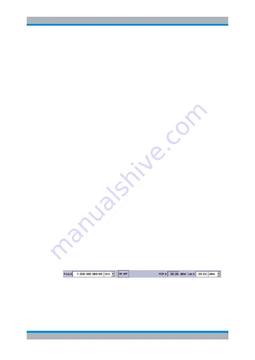
The main characteristics of the RF signal, frequency and level, are permanently displayed
in the header section of the screen and can be directly set in the display fields after the
FREQ (CTRL+F) or LEVEL (CTRL+L) key is pressed. Status messages for the output
signal are displayed in addition to frequency and level.
Operation via Graphical User Interface
●
Functional blocks
Menus are assigned to the specific function blocks in the block diagram. The function
blocks represent elements of signal generation. Function blocks displayed with a blue
frame can be directly switched on and off by means of the TOGGLE ON/OFF (CTRL
Key Features
Содержание 1141.2005.02
Страница 27: ......
Страница 74: ...Preparing for Use R S SMU200A 57 Quick Start Guide 1007 9822 62 13 LXI Configuration ...
Страница 75: ......
Страница 95: ......
Страница 134: ...Manual Operation R S SMU200A 117 Quick Start Guide 1007 9822 62 13 Legend of Front Panel Controls ...
Страница 135: ......
Страница 140: ...Hardware Interfaces R S SMU200A 123 Quick Start Guide 1007 9822 62 13 Fig 1 2 BERT circuit diagram BERT Connector ...
Страница 141: ......
Страница 144: ...Index R S SMU200A 127 Quick Start Guide 1007 9822 62 13 Winbar 89 Windows XP 33 access 34 ...

