Manual Operation
R&S
®
SMU200A
89
Quick Start Guide 1007.9822.62 ─ 13
●
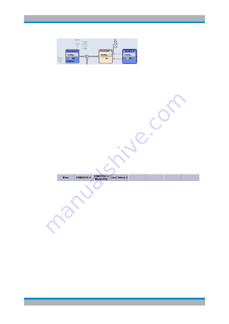
The baseband signal is indicated by a three line arrow, the I- and Q-components of
the signal by a single-line arrow.
●
Addition of signals is indicated by the summation sign.
●
Connections are indicated by a "solder point".
●
Black is used for the generated signal.
●
Green is used for control signals.
The signal flow is configured in the individual menus. User interfaces are configured in:
●
the "Setup > USER Marker /AUX I/O Settings" dialog and
●
the "Setup > Global Trigger/Clock/External Inputs" dialog.
4.2.5 Winbar and Softkeys
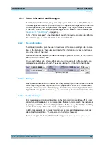
The "Winbar" with eight buttons is displayed below the block diagram. Labelled buttons
represent open menus, the label indicates the menu. If several menus are open, the
button of the currently active menu is displayed in a lighter colour. The buttons also assign
functions to the softkeys of the next lower level for front-panel operation. Up to eight
menus may be open simultaneously. When the ninth menu is opened, the menu that was
opened first is automatically closed.
Some menus, e.g. data and list editor menus, cover the "Winbar" and assign menu-spe-
cific functions to the front-panel softkeys by way of the menu buttons.
Any of the open menus can be activated either with the respective button in the "Win-
bar" or the front-panel softkey. In combination with the keys for menu operation
(CLOSE (ESC), HIDE (CTRL+H) and REARR (CRTL+A)), convenient menu operation
can be ensured.
Working with menus and dialog boxes is described in
4.2.6 Structure of the Dialogs
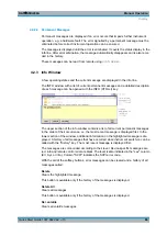
The parameters are set in the menus. Menus are accessed either via the function blocks
in the diagram or by means of the MENU (CTRL+M) key. The menus are displayed on
top of the block diagram.
If the menu buttons assign menu-specific functions to the softkeys, the "Winbar" is hidden.
Display
Содержание 1141.2005.02
Страница 27: ......
Страница 74: ...Preparing for Use R S SMU200A 57 Quick Start Guide 1007 9822 62 13 LXI Configuration ...
Страница 75: ......
Страница 95: ......
Страница 134: ...Manual Operation R S SMU200A 117 Quick Start Guide 1007 9822 62 13 Legend of Front Panel Controls ...
Страница 135: ......
Страница 140: ...Hardware Interfaces R S SMU200A 123 Quick Start Guide 1007 9822 62 13 Fig 1 2 BERT circuit diagram BERT Connector ...
Страница 141: ......
Страница 144: ...Index R S SMU200A 127 Quick Start Guide 1007 9822 62 13 Winbar 89 Windows XP 33 access 34 ...


