Getting Started
R&S
®
SMU200A
70
Quick Start Guide 1007.9822.62 ─ 13
I/Q Mod A block
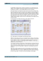
The (first) I/Q modulator is configured in this block. Also the Analog Wideband I/Q mode
can be selected here, which allows external I/Q signals to be directly applied to the I/Q
modulator, i.e. not via the baseband section. If no baseband modules are installed, I/Q
modulation is possible only in the Analog Wideband I/Q mode.
This block can be used to select whether the signal of path A or path B is applied to the
analog I/Q outputs.
I and Q components can also be swapped (I/Q Swap). (Analog) I/Q impairments can be
set in addition. Unlike the impairments in the "AWGN/IMP" block, impairments in the "I/
Q Mod" block also affect the externally applied signals in the Analog Wideband I/Q mode.
The status display in the block shows whether I/Q impairments and/or I/Q swap is active.
I/Q modulation is switched on or off with the TOGGLE ON/OFF key.
Note:
An I/Q modulator provided in the R&S SMU is automatically activated when a
connected baseband source is switched on. The I/Q modulator can also be separately
switched on and off (select the "I/Q Mod" block and press the TOGGLE ON/OFF key).
This permits the following configuration to be obtained with a single-path R&S SMU.
The baseband source generates an I/Q signal that is output via the analog I/Q output. At
the same time, the RF section generates an unmodulated carrier.
I/Q Mod B block
This block controls the I/Q modulator of RF path B. It is displayed only if a second RF
path and two baseband main modules are installed.
Note:
The I/Q modulator B can only be driven by modulation signals from the R&S SMU
baseband section. Operation with external analog I/Q signals is not possible.
RF/A Mod A block
In this block, the RF parameters and the analog modulation modes of path A are set.
The active analog modulation modes are displayed in the block. The TOGGLE ON/
OFF key switches the RF signal on and off. When the RF signal is switched off, the switch
before the RF output symbol is open.
RF settings include:
●
Frequency and reference frequency
●
Attenuator settings.
If required, switching to the high-power mode if a high-power option is installed for
path A.
●
Frequency and level sweep
●
List Mode settings. In this mode, extremely fast frequency and level settings can be
made.
Note:
Numeric values for frequency and level are entered best and quickest with the aid
of the FREQ and LEVEL keys.
Available analog modulation modes:
●
Amplitude modulation
●
Broadband amplitude modulation
●
Frequency modulation (option R&S SMU-B20/B22)
●
Phase modulation (option R&S SMU-B20/B22)
●
Pulse modulation.
RF Section
Содержание 1141.2005.02
Страница 27: ......
Страница 74: ...Preparing for Use R S SMU200A 57 Quick Start Guide 1007 9822 62 13 LXI Configuration ...
Страница 75: ......
Страница 95: ......
Страница 134: ...Manual Operation R S SMU200A 117 Quick Start Guide 1007 9822 62 13 Legend of Front Panel Controls ...
Страница 135: ......
Страница 140: ...Hardware Interfaces R S SMU200A 123 Quick Start Guide 1007 9822 62 13 Fig 1 2 BERT circuit diagram BERT Connector ...
Страница 141: ......
Страница 144: ...Index R S SMU200A 127 Quick Start Guide 1007 9822 62 13 Winbar 89 Windows XP 33 access 34 ...

