Getting Started
R&S
®
SMU200A
69
Quick Start Guide 1007.9822.62 ─ 13
BERT block
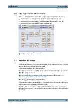
In this block an integrated bit and block error rate tester can be set. The bit error tester
makes it possible to evaluate a signal demodulated and decoded by a DUT by measuring
the bit error rate. The data used to drive the DUT can be generated by the R&S SMU or
an user-defined external source. In addition, the block error rate measurement can be
used to verify CRC checksums.
The TOGGLE ON/OFF key switches the active function(s) of the block on or off. The
functions (BERT and BLER) are activated in the respective menus.
3.4 RF Section
The RF section of the R&S SMU may also contain two paths.
An RF path is configured by installing a frequency option that comprises all required
modules.
One of the following options must be installed.
Frequency options (Path A)
●
R&S SMU-B102 (up to 2.2 GHz)
●
R&S SMU-B103 (up to 3 GHz)
●
R&S SMU-B104 (up to 4 GHz)
●
R&S SMU-B106 (up to 6 GHz)
Frequency options (Path B)
●
R&S SMU-B202 (up to 2 GHz)
●
R&S SMU-B203 (up to 3 GHz)
RF path B can be I/Q-modulated only if the baseband section is equipped with two Base-
band Main Modules R&S SMU-B13.
In addition, each RF path can be equipped with
●
high-power option for higher output levels (R&S SMU-B31/B36)
For detailed information on available options, refer to the R&S SMU data sheet and the
R&S SMU Configuration guide.
Up-to-date information is available at R&S SMU homepage on the internet
www2.rohde-schwarz.com/product/smu200a.html
3.4.1 Description of Individual Diagram Blocks of the RF Section
This section gives an overview of the available blocks and a detailed descritption of their
functions.
RF Section
Содержание 1141.2005.02
Страница 27: ......
Страница 74: ...Preparing for Use R S SMU200A 57 Quick Start Guide 1007 9822 62 13 LXI Configuration ...
Страница 75: ......
Страница 95: ......
Страница 134: ...Manual Operation R S SMU200A 117 Quick Start Guide 1007 9822 62 13 Legend of Front Panel Controls ...
Страница 135: ......
Страница 140: ...Hardware Interfaces R S SMU200A 123 Quick Start Guide 1007 9822 62 13 Fig 1 2 BERT circuit diagram BERT Connector ...
Страница 141: ......
Страница 144: ...Index R S SMU200A 127 Quick Start Guide 1007 9822 62 13 Winbar 89 Windows XP 33 access 34 ...

