background image

R&S

®

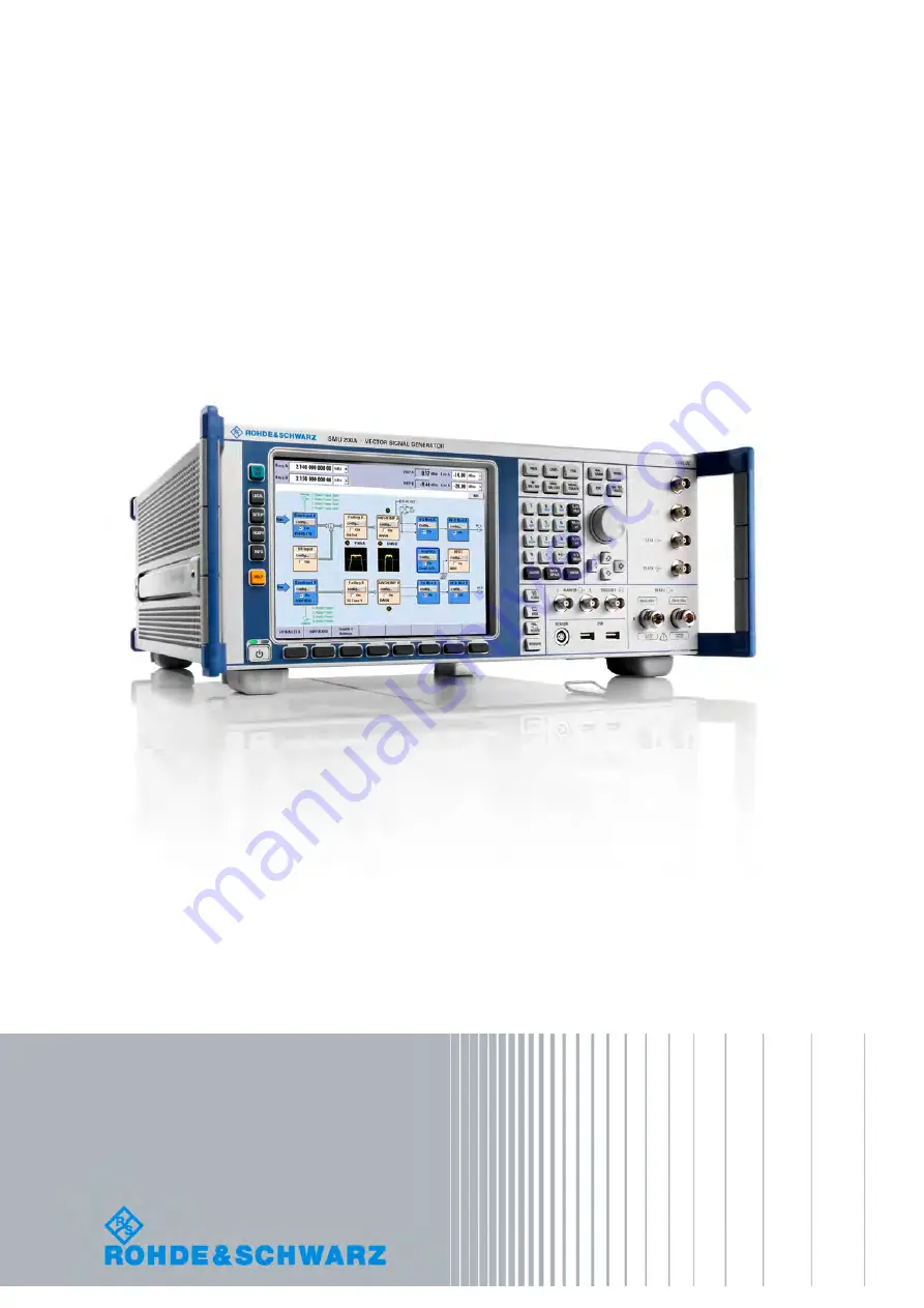
SMU200A

Vector Signal Generator

Quick Start Guide

Quick Start Guide

(:7ðFÌ)

1007.9822.62 ─ 13

Test & Measurement

Содержание 1141.2005.02

Страница 1: ...R S SMU200A Vector Signal Generator Quick Start Guide Quick Start Guide 7ðFÌ 1007 9822 62 13 Test Measurement ...

Страница 2: ...ten by Eric Young eay cryptsoft com and software written by Tim Hudson tjh cryptsoft com Rohde Schwarz would like to thank the open source community for their valuable contribution to embedded computing 2011 Rohde Schwarz GmbH Co KG Muehldorfstr 15 81671 Munich Germany Phone 49 89 41 29 0 Fax 49 89 41 29 12 164 E mail info rohde schwarz com Internet http www rohde schwarz com Printed in Germany Su...

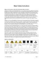
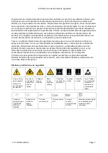
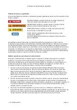
Страница 3: ...f the product The product is used for its designated purpose if it is used in accordance with its product documentation and within its performance limits see data sheet documentation the following safety instructions Using the product requires technical skills and a basic knowledge of English It is therefore essential that only skilled and specialized staff or thoroughly trained personnel with the...

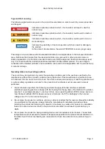
Страница 4: ...he positions specified by the manufacturer without the product s ventilation being obstructed If the manufacturer s specifications are not observed this can result in electric shock fire and or serious personal injury or death Applicable local or national safety regulations and rules for the prevention of accidents must be observed in all work performed 1 Unless otherwise specified the following r...

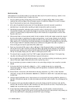
Страница 5: ...at it is in proper operating condition By taking appropriate safety measures and carefully laying the power cable you can ensure that the cable will not be damaged and that no one can be hurt by for example tripping over the cable or suffering an electric shock 6 The product may be operated only from TN TT supply networks fused with max 16 A higher fuse only after consulting with the Rohde Schwarz...

Страница 6: ... damage may occur It is the responsibility of the employer operator to select suitable personnel for operating the products 2 Before you move or transport the product read and observe the section titled Transport 3 As with all industrially manufactured goods the use of substances that induce an allergic reaction allergens such as nickel cannot be generally excluded If you develop an allergic react...

Страница 7: ... sunlight must be avoided Keep cells and batteries clean and dry Clean soiled connectors using a dry clean cloth 3 Cells or batteries must not be short circuited Cells or batteries must not be stored in a box or in a drawer where they can short circuit each other or where they can be short circuited by other conductive materials Cells and batteries must not be removed from their original packaging...

Страница 8: ... regulations must be observed Also observe the relevant safety instructions in the product documentation The improper disposal of hazardous substances or fuels can cause health problems and lead to environmental damage Informaciones elementales de seguridad Es imprescindible leer y observar las siguientes instrucciones e informaciones de seguridad El principio del grupo de empresas Rohde Schwarz c...

Страница 9: ...s imprescindible leer detalladamente y comprender por completo las siguientes informaciones de seguridad antes de usar el producto y respetarlas durante el uso del producto Deberán tenerse en cuenta todas las demás informaciones de seguridad como p ej las referentes a la protección de personas que encontrarán en el capítulo correspondiente de la documentación del producto y que también son de obli...

Страница 10: ...por el fabricante respecto a los estados operativos y posiciones de funcionamiento sin que se obstruya la ventilación Si no se siguen las indicaciones del fabricante pueden producirse choques eléctricos incendios y o lesiones graves con posible consecuencia de muerte En todos los trabajos deberán ser tenidas en cuenta las normas nacionales y locales de seguridad del trabajo y de prevención de acci...

Страница 11: ...red eléctrica Si los productos sin interruptor están integrados en bastidores o instalaciones se deberá colocar el interruptor en el nivel de la instalación 5 No utilice nunca el producto si está dañado el cable de conexión a red Compruebe regularmente el correcto estado de los cables de conexión a red Asegúrese mediante las medidas de protección y de instalación adecuadas de que el cable de conex...

Страница 12: ...o ya se hayan producido condensaciones sobre el producto o en el interior de éste como p ej al desplazarlo de un lugar frío a otro caliente La entrada de agua aumenta el riesgo de choque eléctrico 18 Antes de la limpieza desconecte por completo el producto de la alimentación de tensión p ej red de alimentación o batería Realice la limpieza de los aparatos con un paño suave que no se deshilache No ...

Страница 13: ...hwarz Si se reponen partes con importancia para los aspectos de seguridad p ej el enchufe los transformadores o los fusibles solamente podrán ser sustituidos por partes originales Después de cada cambio de partes relevantes para la seguridad deberá realizarse un control de seguridad control a primera vista control del conductor de protección medición de resistencia de aislamiento medición de la co...

Страница 14: ...s personales o daños en el producto siga las instrucciones de seguridad del fabricante del medio de transporte o elevación utilizado 3 Si se utiliza el producto dentro de un vehículo recae de manera exclusiva en el conductor la responsabilidad de conducir el vehículo de manera segura y adecuada El fabricante no asumirá ninguna responsabilidad por accidentes o colisiones No utilice nunca el product...

Страница 15: ... only be disposed of at a Rohde Schwarz service center or at a suitable depot Normas de Seguridad para Baterías Según BattV Este equipo lleva una batería que contiene sustancias per judiciales que no se debe desechar en los contenedores de basura domésticos Después de la vida útil la batería sólo se podrá eliminar en un centro de servicio de Rohde Schwarz o en un depósito apropiado Consignes de sé...

Страница 16: ...ance with EN 50419 Once the lifetime of a product has ended this product must not be disposed of in the standard domestic refuse Even disposal via the municipal collection points for waste electrical and electronic equipment is not permitted Rohde Schwarz GmbH Co KG has developed a disposal concept for the environmental friendly disposal or recycling of waste material and fully assumes its obligat...

Страница 17: ...ment system stan dards The Rohde Schwarz quality management system is certified according to standards such as ISO9001 and ISO14001 Environmental commitment Energy efficient products J J Continuous improvement in J J environmental sustainability ISO14001 certified environmental J J management system Cher client Vous avez choisi d acheter un pro duit Rohde Schwarz Vous disposez donc d un produit fa...

Страница 18: ...pproximation of the laws of the Member States relating to electrical equipment for use within defined voltage limits 2006 95 EC relating to electromagnetic compatibility 2004 108 EC Conformity is proven by compliance with the following standards EN 61010 1 2001 EN 61326 1 2006 EN 61326 2 1 2006 EN 55011 2007 A2 2007 EN 61000 3 2 2006 EN 61000 3 3 1995 A1 2001 A2 2005 For the assessment of electrom...

Страница 19: ...rument up to date and to be informed about new application notes related to your instrument please send an e mail to the Customer Support Center stating your instrument and your wish We will take care that you will get the right information Europe Africa Middle East Phone 49 89 4129 12345 customersupport rohde schwarz com North America Phone 1 888 TEST RSA 1 888 837 8772 customer support rsa rohde...

Страница 20: ...1 7 Front Panel Connectors 17 2 2 Rear Panel Tour 19 2 2 1 Description of the Connectors 20 2 3 Putting into Operation 24 2 3 1 Unpacking and Checking the Instrument 25 2 3 2 Placing or Mounting the Instrument 26 2 3 3 Connecting the Instrument to the AC Supply 27 2 3 4 Starting the Instrument 27 2 3 4 1 Standby and Ready state 28 2 3 4 2 Start Display and Booting 28 2 3 4 3 Function Check 28 2 3 ...

Страница 21: ... Ultr VNC 44 2 8 Using Virus Protection Software 50 2 9 LXI Configuration 51 2 9 1 LXI Browser Interface 53 2 9 2 LAN Configuration 54 2 9 2 1 Advanced LAN Configuration 55 2 9 2 2 Ping 56 3 Getting Started 59 3 1 Brief Introduction to the Instrument s Concept 59 3 2 Applications of the Instrument 61 3 2 1 Generation of digitally modulated signal 61 3 2 2 Two Baseband Generators One RF Path 63 3 2...

Страница 22: ...logs 89 4 2 7 Graphical Display of Output Signal Characteristics 90 4 3 Accessing Dialogs 91 4 4 Setting Parameters 92 4 4 1 Working with the Cursor 93 4 4 2 Selecting a Control Element 94 4 4 3 Switching Parameters On Off 94 4 4 4 Entering a Value 94 4 4 5 Working with Units 96 4 4 6 Selecting a Value from a List 97 4 4 7 Terminating Entries with Confirmation 97 4 4 8 Restoring the Previous Value...

Страница 23: ...2 13 4 8 Legend of Front Panel Controls 114 4 8 1 Front Panel Key Emulation 116 4 8 2 On screen Keyboard 116 A Hardware Interfaces 119 A 1 GPIB Bus Interface 119 A 2 AUX I O Connector 120 A 3 Monitor Connector MONITOR 122 A 4 BERT Connector 122 Index 125 ...

Страница 24: ...and an example of setup are described The manual includes also general information e g Safety Instructions Operating Manuals The Operating Manuals are a supplement to the Quick Start Guide Operating Manuals are provided for the base unit and each additional software option These manuals are available in PDF format in printable form on the Documentation CD ROM delivered with the instrument In the O...

Страница 25: ...derd in printed form see ordering information in the data sheet Service Manual This Service Manual is available in PDF format in printable form on the Documentation CD ROM delivered with the instrument It describes how to check compliance with rated specifications on instrument function repair troubleshooting and fault elimination It contains all information required for repairing the instrument b...

Страница 26: ... are enclosed by quotation marks KEYS Key names are written in capital letters File names commands program code File names commands coding samples and screen output are distinguished by their font Input Input to be entered by the user is displayed in italics Links Links that you can click are displayed in blue font References References to other parts of the documentation are enclosed by quotation...

Страница 27: ......

Страница 28: ...enerator functions and introduces the operating concept Detailed operating instruc tions and an overview of menus follow in chapter 4 Manual Operation on page 79 For all reference information concerning manual and remote control of the instrument refer to the online help system or its printed printable version A more detailed description of the hardware connectors and interfaces is also part of th...

Страница 29: ...and assistance For more information refer to chapter Instrument Settings in the Operating Manual PRESET Sets the instrument to a defined state see chapter 2 3 4 4 Default Set tings on page 29 LOCAL Switches from remote control to local manual control SETUP Opens the Setup dialog for configuring presettings HCOPY Opens the Hardcopy menu for configuring and starting printing INFO Displays status mes...

Страница 30: ...sages Brief error messages To access an window with detailed information for a message use the INFO key Block diagram The block diagram shows the current configuration and the signal flow in the gener ator with the aid of function blocks containing an on off switch Selecting a function block opens a list of associated setting menus Active menus info windows and graphs are displayed on top of the b...

Страница 31: ...e the last switch off RF OFF is displayed in the header next to the Frequency field LEVEL Activates level entry In the two path mode the level entry field that was active last is activated Pressing the key a second time activates level entry for the second path MOD ON OFF Switches the modulations on and off In the two path mode the MOD ON OFF key switches all modulations off Pressing the key again...

Страница 32: ...fts the entry cursor from the header display to the previously active menu or to the previously highlighted block in the block diagram if no menu is active Shifts the cursor from a function block in the diagram to the first item in the Win bar If no menus are open the current cursor position remains unchanged TOGGLE Switches highlighted elements or a function block on and off Switches between two ...

Страница 33: ... function depends on the time at which the UNIT key is used during parameter entry see chapter 4 4 5 Working with Units on page 96 For unit free values the X1 key is equivalent to ENTER It confirms the previous entry and deactivates the input field _ Adds a blank in a character input field Enters special characters Toggles through the available characters if the key is pressed sev eral times in a ...

Страница 34: ...g lists if the edit mode is activated Note Turning or pressing the rotary knob is equivalent to pressing the UP and DOWN keys or the ENTER key in the keypad NAVIGATION KEYS The navigation keys consist of 4 arrow keys which are used for navigation alternatively to the rotary knob UP DOWN KEYS The up and down arrow keys do the following In a numeric edit dialog box increase or decrease the instrumen...

Страница 35: ...is sible back feed is specified in the data sheet TRIGGER 1 Input for triggering digital modulations standards and ARB For more information see chapter Global Trigger Clock Input Settings in the Operating Manual MARKER 1 2 Outputs 1 and 2 for triggering and control of external devices with user definable marker signals The instrument provides four outputs for marker signals Marker signals 1 to 3 a...

Страница 36: ...omatically determined e g for compensating the frequency response of cables The power sensors are connected by inserting the male connector To disconnect hold the connector by its sleeve Pulling on the sensor cable will not release the sensor con nector 2 2 Rear Panel Tour This section gives an overview of connectors on the rear panel of the instrument Each connector is briefly described and a ref...

Страница 37: ...d control of external devices Marker outputs are permanently assigned see MARKER 1 2 on page 18 MARKER 1 MARKER 2 Rear Panel Connectors for path A option R S SMU B81 and path B option R S SMU B82 These options are recommended for use of the instrument in a 19 rack Installing the instrument in a 19 rack requires a rack adapter or an adapter for telescopic sliders refer to data sheet for order numbe...

Страница 38: ...to the AC Sup ply on page 27 I OUT Q OUT path A or path B Direct output or Differential non inverting output for analog I Q signal Option option R S SMU B16 is required I OUT BAR Q OUT BAR path A or path B Differential inverting output for analog I Q signal I Q DATA CLOCK Rear Panel Connectors for path A option R S SMU B81 and path B option R S SMU B82 This options are recommended for use of the i...

Страница 39: ...f type B device USB This port is reserved for future extensions MONITOR Connector for external monitor see chapter 2 4 2 Connecting a Moni tor on page 32 For description of this connector refer to chapter A 3 Monitor Connector MONI TOR on page 122 AUX I O Parallel input output for data signals as well as settable trigger and control signals of the baseband Input for device trigger Assignment of th...

Страница 40: ...9 rack Installing the instrument in a 19 rack requires a rack adapter or an adapter for telescopic sliders refer to data sheet for order number See also chapter 2 3 2 Placing or Mounting the Instrument on page 26 LO IN LO OUT Local oscillator input and output LO IN Input for external LO signals LO OUT Output for internal LO signals CLOCK OUT Output for internal clock signal This connector is used ...

Страница 41: ...lescopic sliders refer to data sheet for Order No See also chapter 2 3 2 Placing or Mounting the Instrument on page 26 2 3 Putting into Operation This section describes the basic steps to be taken when setting up the R S SMU for the first time Shock hazard Do not open the instrument casing As a rule normal operation of the instrument does not require opening the casing Observe the general safety i...

Страница 42: ...discharge to avoid damage to electronic com ponents in the modules For details refer to the safety instructions at the beginning of this manual EMI impact on measurement results Electromagnetic interference EMI can affect the measurement results To avoid any impact make sure that the following conditions are met Use suitable double shielded cables Do not use USB connecting cables exceeding 1 m in ...

Страница 43: ... conditions either on a bench top or in a rack using a rack adapter kit order number see data sheet Bench Top Operation If the R S SMU is operated on a bench top the surface should be flat The instrument can be used in horizontal position standing on its feet or with the support feet on the bottom extended Risk of injury The feet may fold in if they are not folded out completely or if the instrume...

Страница 44: ...lly equivalent power supply unit Switching off the AC power You can leave the AC power on permanently to preserve your last instrument settings Switching off is required only if the instrument must be completely disconnected from all power supplies Starting up instruments with power switch 1 Connect the instrument to the AC supply 2 To turn the power on press the main power switch to position I On...

Страница 45: ...tes for a few seconds the installed BIOS version and the processor characteristics The instrument boots the operating system starts the instrument firmware and automat ically performs a selftest If the previous session was terminated regularly the instrument uses the last setup with the relevant instrument settings Once the startup procedure has been terminated the block diagram opened in the pre ...

Страница 46: ...orresponding dialog e g all digital modulation settings in the Custom Digital Mod dialog These settings are identical to those which are called up using the PRESET key Preset the instrument to a predefined state The PRESET key calls up a defined instrument setup All parameters and switching states are preset also those of inactive operating modes The default instrument settings provide a reproduci...

Страница 47: ...strument states can be stored and called up in the File dialog 2 3 5 Shutting Down the Instrument To shut down the R S SMU proceed as described below Risk of losing data If you switch off the running instrument using the rear panel switch or by disconnecting the power cord the instrument loses its current settings Furthermore program data may be lost Press the ON STANDBY key first to shut down the...

Страница 48: ... devices there is almost no limit to the expansions that are possible with the R S SMU The following list shows various USB devices that can be useful Memory stick for easy transfer of data to from a computer e g firmware updates CD ROM drives for easy installation of firmware applications Keyboard or mouse to simplify the entry of data comments file names etc Printer for printing out measurement ...

Страница 49: ...te printer driver is installed If required printer driver installation is initiated using Windows XP s Add Printer wizard A printer driver needs to be installed only once You can load updated and improved driver versions or new drivers from an installation disk USB memory stick or another external storage medium If the instrument is inte grated in a network you can also install driver data stored ...

Страница 50: ...programs that Rohde Schwarz has tested for compatibility with the instrument software The drivers and programs used on the instrument under Windows XP have been adapted to the instrument Existing instrument software must always be modified using only update software released by Rohde Schwarz The following program packages have been tested R S Power Viewer virtual power meter for displaying results...

Страница 51: ...ating system boots and the instrument firmware is started auto matically 2 5 3 Login Windows XP requires that users identify themselves by entering a user name and pass word in a login window The instrument provides a factory installed auto login function i e login is carried out automatically in the background The ID used for autologin has administrator rights so that printer and network installa...

Страница 52: ...o configure the LAN interface It includes the following topics chapter 2 6 1 Connecting the Instrument to the Network on page 35 chapter 2 6 2 Assigning the IP Address on page 36 LXI The R S SMU complies with LXI Class C LXI gives you direct access to the LAN settings described below Accessing Operating System The operating system can only be accessed if an external keyboard and or a mouse is conn...

Страница 53: ...tes the required drivers The network card can be operated with a 10 100 1000 Mbps Ethernet IEEE 802 3u inter face 2 6 2 Assigning the IP Address Depending on the network capacities the TCP IP address information for the instrument can be obtained in different ways If the network supports dynamic TCP IP configuration using the Dynamic Host Con figuration Protocol DHCP all address information can be...

Страница 54: ...o select Use the following DNS server addresses and enter your own DNS addresses For more information refer to the Windows XP Help 2 6 3 Using computer names Alternatively to the IP address each PC or instrument connected in a LAN can be accessed via an unambiguous computer name Each instrument is delivered with an assigned computer name but this name can be changed Querying and changing a compute...

Страница 55: ...k administrator However the hard disk of a computer also connected to the network can be accessed from the instrument relatively easily The only precondition is that the directory on the remote computer that the instrument should access is enabled for remote access Sub sequently this directory is accessed from the instrument using a Windows XP search function This procedure is also of importance f...

Страница 56: ...r an overview of the instrument s operating concept and the different ways to control and operate the instrument see chapter 3 1 Brief Introduction to the Instrument s Con cept on page 59 There are different ways to establish a remote access connection to the signal generator but all of them require an established LAN connection between the instrument and the remote computer The simplest way to re...

Страница 57: ... identifies the accessing user When the connection is set up with Ultr VNC direct control on the instrument is possible while remote access is established For return to direct operation on the instrument the connection must be cut After cutting the connection it is still enabled and can be established again any time The connection is disabled only after deactivation of the program This section giv...

Страница 58: ...111 11 1 The VNC Authentication screen appears 4 Enter the password and select OK The default password is instrument After the connection is established the current signal generator screen with the block diagram is displayed and the instrument can be remote accessed from the remote computer 2 7 2 Remote Desktop Connection Remote Desktop is a Windows application which can be used to access and cont...

Страница 59: ...rosoft offers the Remote Desktop Client as an add on Enabling remote desktop control on the instrument 1 Press the Windows key to access the operating system 2 Open the Control Panel by selecting Start Settings Control Panel 3 Select System and switch to the Remote tab 4 Under Remote Desktop activate the Allow users to connect remotely to this com puter option Note Remote Desktop access and firewa...

Страница 60: ...e the connection settings in the Remote Desktop Connection dialog box Click the Options button The dialog box is expanded to display the configuration data 2 Customize the settings On the Experience tab Select the appropriate connection to optimize the connection speed To improve the performance you can deactivate options you do not require under Allow the following On the Local Resources tab If y...

Страница 61: ...op disable the Allow users to connect remotely to this com puter option and confirm with OK The connection is disabled it is no longer possible to access the instrument via Remote Desktop 2 7 3 Remote Access via Ultr VNC Ultr VNC is an application which can be used to access and control the instrument from a remote computer through a LAN connection The program is included in operating sys tem Linu...

Страница 62: ...perating system see Setting up the VNC connection on the Windows remote computer on page 49 Enabled Direct Control The direct control of the instrument is not disabled and the instrument can be controlled from the front panel and via the remote computer alternately Installing the Ultr VNC application 1 Download the program from the internet and copy it to a directory that can be accessed 2 On the ...

Страница 63: ...the Additional Task Panel enable all entries A successful installation is indicated by a message At the same time a warning is displayed stating that a password must be set 4 Select OK The Default Local System Properties panel opens Remote Access via an External Controller ...

Страница 64: ...nd the user defined password are the prerequisites to enable remote access on the remote computer Terminated connection is indicated by changed icon color Configuring Internet Connection Firewall for VNC Connection To enable remote access of an instrument in a local network via VNC connection the connection must be specifically permitted in the firewall 1 Press the Windows key to access the operat...

Страница 65: ...ble per default for Linux Unix operating systems 1 Start a Web browser on the remote computer and enter the IP address of the instru ment 2 Enter the following address vnc IP address of the instrument e g vnc 192 168 1 1 A dialog is opened and the password for the remote VNC connection is requested 3 Enter the password as defined in the Default Local System Properties panel of the Ultr VNC program...

Страница 66: ...ing the mouse and keyboard Enabled Direct Control The direct control of the instrument is not disabled and the instrument can be controlled from the front panel and via the remote computer alternately Terminating VNC Connection The remote access via VNC connection can be terminated either on the R S SMU or on the external PC Terminating the connection does not disable it It can be established agai...

Страница 67: ...2 8 Using Virus Protection Software Virus protection software Symantec Antivirus 10 1 7 7000 has been successfully tested for compatibility with the instrument software on R S Signal Generator However Symantec Antivirus may affect the behaviour of the instrument in terms of set tling time or stability Symantec Antivirus 10 1 7 7000 has been subjected to detailed tests with R S Signal Generator and...

Страница 68: ...ed on standard Ethernet technology LXI is intended to be the LAN based successor to GPIB combining the advantages of Ethernet with the simplicity and familiarity of GPIB Like GPIB LXI determines and standardizes the way the instrument behaves in a LAN The LXI implementation by the R S Signal Generators allows you to change certain LAN settings to reset the LAN connection as well as to easy identif...

Страница 69: ...are additionally equipped with the eight channel hardware trig ger bus LVDS interface defined in the LXI standard For information about the LXI standard refer to the LXI website at http www lxistan dard org See also News from Rohde Schwarz article 2006 II 190 Instruments of classes A and B can generate and receive software triggers via LAN mes sages and communicate with each other without involvin...

Страница 70: ...tor Signal Generator Negotiation Auto Detect VXI 11 Discovery Enabled The LAN settings are configured using the instrument s LXI Browser Interface 2 9 1 LXI Browser Interface The instrument s LXI browser interface works correctly with all W3C compliant browsers Typing the instrument s host name or IP address in the address field of the browser on your PC e g http 10 113 10 203 opens the Instrument...

Страница 71: ...dicates that no LAN cable is connected The status of the LAN connection is also indicated by the LAN Status indicator in the LXI Status dialogbox The Device Indicator setting is not password protected For further information see section LXI Status in the Operating Manual The navigation pane of the browser interface contains the following control elements LAN Configuration opens the LAN Configurati...

Страница 72: ...the instrument IP address Changing the LAN configuration is password protected The password is LxiWebIfc notice upper and lower case characters This password cannot be changed in the cur rent firmware version The links at the bottom of the LAN Configuration page open other pages Ping Client provides the ping utility to verify the connection between the instrument and other devices Advanced LAN Con...

Страница 73: ...isms are permitted 2 9 2 2 Ping Ping is a utility that verifies the connection between the LXI compliant instrument and another device The ping command uses the ICMP echo request and echo reply packets to determine whether the LAN connection is functional Ping is useful for diagnosing IP network or router failures The ping utility is not password protected To initiate a ping between the LXI compli...

Страница 74: ...Preparing for Use R S SMU200A 57 Quick Start Guide 1007 9822 62 13 LXI Configuration ...

Страница 75: ......

Страница 76: ...ent upper frequency limit Up to two generators can also be installed in the baseband section They generate complex signals in realtime and are equipped with an arbitrary waveform gen erator The R S SMU provides an entirely digital baseband section for generating I Q signals and an RF section with I Q modulator The instrument uses I Q vector modulation Dig ital data streams are converted to an I Q ...

Страница 77: ...strument Fig 3 1 Block diagram of a fully equipped two path R S Signal Generator With the aid of the rotary knob the user can navigate in the block diagram and the dialogs and can operate the instrument with one hand The cursor is moved line by line through the block diagram or dialog Turning the button clockwise advances the cursor The selected block can be activated or deactivated with the TOGGL...

Страница 78: ...ment from a remote computer Both the R S SMU and the computer are connected in a LAN Remote access in contrast to remote control does not use remote control commands but a separate software which is installed on the remote computer After its start the software simulates the user interface of the instrument The instrument can thus be oper ated from the remote computer as on the unit itself The indi...

Страница 79: ...os can be created with the aid of a fading module option R S SMU B14 Fading Simulator Fig 3 2 Operation of I Q modulator with I Q signals from the internal baseband section Externally generated I Q signal The I Q signal is generated by an external instrument and coupled in via the baseband input module option R S SMU B17 Baseband Input The baseband input module is capable of processing analog I Q ...

Страница 80: ... of the I Q modulator can be utilized The various capa bilities of the baseband section AWGN addition of signals etc are disabled however Fig 3 4 Operation of I Q modulator with external analog I Q signals directly applied to the I Q modulator 3 2 2 Two Baseband Generators One RF Path Examples of the possible applications of an instrument equipped with two baseband generators and one RF path are A...

Страница 81: ...nerator with two baseband generators and one RF path 3 2 3 One Baseband Path and Two RF Paths An examples of the possible applications of an instrument equipped with one baseband path and two RF paths is Generation of a modulated signal on path A and a CW interferer on path B Fig 3 6 Operation of R S Signal Generator with one baseband generator and two RF paths Applications of the Instrument ...

Страница 82: ...l and contains the hard ware for generating and processing I Q signals The baseband section may contain two paths For detailed information on available options refer to the R S SMU data sheet and the R S SMU configuration guide Up to date information is available at R S SMU homepage on the internet http www2 rohde schwarz com product smu200a html Baseband generator option R S SMU B10 The generator...

Страница 83: ...e digital baseband interface with various formats Baseband main module option R S SMU B13 The baseband main module can be installed twice for each of both paths A and B respectively At the end of the baseband path the digital signal is converted to an analog I Q signal The analog I Q signal is fed to the I Q modulator of the RF path This module also routes signals to the analog I Q outputs The mod...

Страница 84: ...ront panel see TOGGLE on page 15 switches the currently selected block on or off A detailed description of the blocks is provided below Baseband A block In this block the first baseband source is configured and activated The block is dis played only if a baseband generator is available in the instrument Depending on the installed software options various digital standards user configured digital r...

Страница 85: ...r off Note Under certain signal routing conditions only one fader can be activated AWGN IMP A block This block is displayed only if a baseband main module is installed In this block digital I Q impairments for the baseband path can be set With the aid of the software for AWGN generation option R S SMU K62 an additive noise signal can be produced AWGN and impairments can be activated independently ...

Страница 86: ...on that comprises all required modules One of the following options must be installed Frequency options Path A R S SMU B102 up to 2 2 GHz R S SMU B103 up to 3 GHz R S SMU B104 up to 4 GHz R S SMU B106 up to 6 GHz Frequency options Path B R S SMU B202 up to 2 GHz R S SMU B203 up to 3 GHz RF path B can be I Q modulated only if the baseband section is equipped with two Base band Main Modules R S SMU ...

Страница 87: ... be obtained with a single path R S SMU The baseband source generates an I Q signal that is output via the analog I Q output At the same time the RF section generates an unmodulated carrier I Q Mod B block This block controls the I Q modulator of RF path B It is displayed only if a second RF path and two baseband main modules are installed Note The I Q modulator B can only be driven by modulation ...

Страница 88: ...ath is installed Available analog modulation modes Amplitude modulation Pulse modulation 3 5 Example of Setup This section provides an example on how to configure the instrument to generate and display a simple QPSK modulated signal Configuring and displaying a QPSK modulated signal To generate and display a QPSK modulated signal proceed as follow 1 Activate default preset state Press the PRESET k...

Страница 89: ... 1007 9822 62 13 a Turn the rotary knob and select the Baseband A block b Press the rotary knob to open the menu where the digital modulation can be selected different modulation modes are available depending on the options installed Example of Setup ...

Страница 90: ...and highlight Custom Digital Mod Press the rotary knob to open the Custom Dig Mod dialog d Turn the rotary knob to select parameter Symbol Rate press the rotary knob to allow editing and enter the preffered symbol rate with the aid of the numeric key pad and the unit keys Example of Setup ...

Страница 91: ...b to select parameter Coding Press the button to open the selection list Turn the rotary knob to select Off and press the knob to activate the selected item f Use the rotary knob in the same way to set Modulation Type QPSK and Fil ter Root Cosine with Roll Off Factor 0 3 Example of Setup ...

Страница 92: ... 1007 9822 62 13 g Finally select State and press the rotary knob to switch on the digital modula tion h Press the DIAGRAM key to display the complete block diagram To indicate the active state the Baseband block is displayed in blue Example of Setup ...

Страница 93: ...put 3 Set frequency and level and activate RF signal a Press the FREQ key to activate the editing mode for frequency entry The Fre quency entry field in the header section of the display is highlighted Enter the frequency using the numeric keypad and terminate the entry by press ing a unit key b Press the LEVEL key and enter the level settings in the same way c Press the DIAGRAM key to display the...

Страница 94: ...art Guide 1007 9822 62 13 4 Select graphics display of I Q signal a Turn the rotary knob to select the Graphics block and open the respective menu b Select State On with the rotary knob to activate display of the I Q diagram Example of Setup ...

Страница 95: ......

Страница 96: ...e gives a permanent overview of characteristics of the generated signal and of the current instrument state Numerous online help func tions support user settings Block diagram The block diagram is the core of the operating concept A graphics display shows the current configuration and the signal flow in the form of a block diagram All graphical elements can be accessed for operation An element is ...

Страница 97: ... shown Menu tree The menu tree can be opened and closed with the MENU CTRL M key The menu tree is organized in the same way as the directories under Windows The function blocks correspond to the first directory level the menus to subdirectories Operation corresponds to the Windows concept To offer the user a familiar environment operation is very similar to operation of Windows user interfaces All...

Страница 98: ...peration at all times Winbar The Winbar gives an overview of menus and simplifies their access The menus are displayed on top of the block diagram but they can be hidden with the aid of the HIDE CTRL H key i e displayed in the form of a button in the Winbar at the lower end of the screen They can be displayed again in full size by a keystroke REARR CTRL A key This makes room on the screen for othe...

Страница 99: ...is part of a comprehensive online help function which can be called by means of an index a content tree or the Previous Next buttons Info line with messages for indication of the current instrument state A great variety of different messages such as status messages error messages warn ings or information are displayed in the header field of the screen With the aid of the INFO CTRL I key help pages...

Страница 100: ...allows a fast check of signal characteristics Zoom functions and the insertion of a reference trace permit in depth evaluation without an external analyzer being required 4 2 Display The display shows the current signal generator state and offers graphical elements for direct operation It is divided into three sections The frequency and level display with info line indicates the main output signal...

Страница 101: ...ge 85 are displayed in the header field of the screen The display may vary depending on the instrument s operating mode In the case of two path instruments the RF information for the two paths is displayed in two lines In the sweep mode the current frequency or level of the output signal is displayed The status message SweepMode is displayed in the info line In the list mode neither the current fr...

Страница 102: ... info line or in the info line itself On two path instruments all states that can occur independently in the two paths are displayed separately for each path The associated path is indicated in the info line 4 2 2 2 Messages Messages indicate errors in the instrument They are displayed in the info line in different colors depending on their importance and display duration Errors e g no calibration...

Страница 103: ...e upper section of the info window contains a list of all current permanent messages in the order of their occurrence i e the most recent message is displayed first In the lower section of the window additional information on the highlighted message is dis played A history of all messages that have occurred since instrument switch on can be called with the History key The most recent message is di...

Страница 104: ...block diagram shows provided options signal configuration and the currently selected signal flow of the generator with inputs and outputs used Signal generation can be completely operated from the block diagram The highlighted function block can be directly switched on and off with the TOGGLE ON OFF CTRL T key Pressing the Enter opens the associated setting menu 4 2 4 1 Function Blocks in the Bloc...

Страница 105: ...e currently used inputs and outputs of the signal generator Unused inputs and outputs are not shown The lines indicate the signal flow Symbols and labels refer to the corresponding inputs and outputs on the front and rear panel of the signal generator The direction input or output is indicated by an arrow Example The symbols indicate the inputs for the analog I and Q signal In case of configurable...

Страница 106: ...lso assign functions to the softkeys of the next lower level for front panel operation Up to eight menus may be open simultaneously When the ninth menu is opened the menu that was opened first is automatically closed Some menus e g data and list editor menus cover the Winbar and assign menu spe cific functions to the front panel softkeys by way of the menu buttons Any of the open menus can be acti...

Страница 107: ... parameters are organized in menu areas A menu area is framed and labelled with the function common to all parameters Example Impairments Each of the setting fields is assigned a parameter name The kind of setting varies depending on the parameter to be set Some settings can only be made in a specific configuration If setting is not permitted with the specific configuration selected the respective...

Страница 108: ...GRAM CTRL D and REARR CTRL A keys on the front panel For a quick access to the dialogs use one of the following alternative methods Displaying the block diagram or a dialog in the foreground 1 Press the DIAGRAM CTRL D key to move the cursor to the block diagram All active menus are minimized and displayed in the form of Winbar buttons 2 Press the associated softkey CTRL F1 F8 to display the dialog...

Страница 109: ...S SMU offers several and sometimes alternative possibilities for setting param eters Operation is possible from the front panel with the aid of a mouse and or from a PC keyboard The examples whitin this description focus on the operation from the front panel For more information refer to chapter 4 8 Legend of Front Panel Controls on page 114 for an overview of key functions and a cross reference b...

Страница 110: ...hapter 4 4 2 Selecting a Control Element on page 94 chapter 4 4 3 Switching Parameters On Off on page 94 chapter 4 4 4 Entering a Value on page 94 chapter 4 4 5 Working with Units on page 96 chapter 4 4 6 Selecting a Value from a List on page 97 chapter 4 4 7 Terminating Entries with Confirmation on page 97 chapter 4 4 8 Restoring the Previous Value on page 98 4 4 1 Working with the Cursor After t...

Страница 111: ... the menu tree a parameter in the menu or an entry in a list or table is concerned To activate an element put the cursor on it An active element is highlighted by a blue frame 4 4 3 Switching Parameters On Off A parameter can be activated and deactivated using a button or a check box 1 Select the parameter 2 To change the state of a parameter use the Enter function of the different control media P...

Страница 112: ...ing the LEFT RIGHT arrow keys The cursor is displayed in green 3 Click on a numeric key to insert a new value Editing a value in the overwrite mode 1 Activate the editing mode 2 Set the cursor on the numeric digit to be changed using the LEFT RIGHT arrow keys The cursor is displayed in blue and the number to be replaced is highlighted 3 Click on a numeric key to overwrite the highlighted value Var...

Страница 113: ...er 2 Press a UNIT key on the front panel 3 Select a Unit in the selection field next to the parameter value 4 4 5 Working with Units The unit of a parameter is displayed next to the value When the parameter is edited the unit is selected either from the list or by means of the front panel keys When the entry is completed the unit can be changed In this case the value remains unchanged but is autom...

Страница 114: ... for the selected parameter To select a item from a list proceed as follow 1 Press ENTER key to open the list 2 Use one of the following alternatives to navigate through the list a Turn the rotary knob or use the UP DOWN arrow keys The selected item is highlighted b Press TOGGLE ON OFF key several times until the preferred entry is displayed in the selection field 3 To confirm the selection press ...

Страница 115: ...tion is interrupted to allow the user to make further settings Calculation is restarted with the RECALCULATE key and the modulation is switched on again when the calculation is completed Preventing recalculation If an instrument function requires several parameter settings switch the function off to prevent a recalculation Enable the function after the entire configuration of the settings have bee...

Страница 116: ...n All previous values are restored 4 5 Editors The R S SMU provides user friendly editors for defining data lists as well as control and marker signals Lists containing frequency and level value pairs are used for the list mode and the user defined level correction Internally generated data lists can be used for digital modulation and digital standards the same applies to internally defined contro...

Страница 117: ...ng list can be edited in the insert or overwrite mode use the INSERT key to toggle between this two modes Terminate the entry by pressing a UNIT key 4 To select a row select the GoTo button and press the ENTER key Use the numeric keys to enter the row index in the entry field and press the ENTER key to confirm the entry The cursor moves to the selected row 5 To insert a new row in the table select...

Страница 118: ... corresponds to a file size of approx 268 Mbyte While it is being pro cessed the file is continuously automatically buffered When the dialog is exited the file is automatically saved with the new values i e there is no extra Save button Depending on the size of the file saving may take some time Editing an existing data list 1 To access a data editor and open an existing data list for editing use ...

Страница 119: ...s a hexadecimal value To increase readability the hexadecimal values in turn are displayed in pairs of two The hex functions are auto matically assigned to the numeric keys at the front panel 7 To save the data list press the ESC key The list is saved automatically when the dialog is closed Creating a new data list 1 To create an empty data list in the individual menu select List Management Select...

Страница 120: ...es in a table The actual graphic definition of the control signals occurs in the center area of the editor Each control signal is represented by means of a colored line along the bit axis A cursor can be shifted alongside this line and marks the position where a ramp is to be set The color of the cursor changes depending on the current function Use the ENTER key to switch over between the colors a...

Страница 121: ... length of the definition range the length is adjusted automatically 3 Configure the control and marker signals see Handling of Ramps on page 105 4 Define length of control list Custom Dig Mod only Select the Total List Length entry field and press the ENTER key Enter the length by means of the numeric keys and confirm the entry The control list length is defined 5 Zoom displayed range Custom Dig ...

Страница 122: ...w low or high high transition as in the example i e it will have no effect on the control signal in this configuration However the ramp remains saved and its position is indicated by a dashed line If another change produces effective transition this ramp will be regenerated 2 Shift a ramp An existing ramp can be shifted to any positions The transitions are adjusted accord ingly Use the arrow keys ...

Страница 123: ...f the new control list 2 To open the control list for editing select the associated button BB Cust Dig Mod List Management Select Control List to Edit Edit Control List and select an existing control list 4 6 How to Use the Help System The R S SMU is equipped with a context sensitive help function A help page is available for each parameter and can be called any time during instrument operation Co...

Страница 124: ... a plus sign 2 To display a help topic press the ENTER key The corresponding help topic is displayed Navigating in the help topics 1 To scroll through a page use the UP DOWN arrow keys 2 To jump to the linked topic press the link text 3 Use the Previous or Next links to jump to the corresponding topic 4 Use the Scroll Right or Scroll Left buttons to shift the indicated area of the navi gation wind...

Страница 125: ...mory stick is connected to the USB interface and is assigned the E drive In the case of a connected network all network drives that can be accessed are available The files are accessed in a Save Recall dialog in the individual menus The files are differentiated according to their extensions each type of file is assigned a specific file content The extension is usually of no consequence to the user...

Страница 126: ...r data 1 To access an editable user data file select the Save Recall or File Manger function in the individual dialog 2 To access a loadable data file select the Select New or File Manager function in the individual dialog 3 To access the File Manager function press the SETUP CTRL E key and select Save Recall File Manager A File Select window for loading saving or creating a file or the File Manag...

Страница 127: ...also offer files containing prede fined contents These files are saved to a specific directory on system drive for this rea son this directory cannot be chosen from the File Select menu Example The following example shows the File Select menu of the GSM EDGE digital standard when Recall Predefined Frames is selected Working with the File Select dialog 1 Access the File Select dialog see Accessing ...

Страница 128: ...ll files selection or a specific selection of files See chapter 4 7 2 1 Exten sions for User Files on page 112 for an overview of the supported file extensions The available drives and directories and the files of the selected directory are displayed The currently selected path is displayed above the windows If the area is opened several times the path last selected is displayed Unlike the File Se...

Страница 129: ...ents File suffix Instrument State Settings Instrument settings savrcl User Correction List User defined level correction values uco List Mode List User defined frequency level value pairs lsw Frequency Response Correc tion Settings User defined frequency response correction file frc Arbitrary Waveform Generator Waveform ARB waveforms ARB multi segment waveforms wv Waveform ARB multi carrier settin...

Страница 130: ...00 menu cdma2k TD SCDMA2000 Settings Complete setting of the TD SCDMA2000 menu tdscdma Settings Test Model for TD SCDMA2000 tdtmd 1xEV DO Settings Complete setting of the 1xEV DO menu evdo IEEE 802 11 WLAN Settings Complete setting of the IEEE 802 11 WLAN menu wlan IEEE 802 11 n WLAN Settings Complete setting of the IEEE 802 11n WLAN menu wlann Settings Beamforming data bmf IEEE 802 16 WiMAX Setti...

Страница 131: ...s all key functions available on the front panel Key combinations used on the PC keyboard to trigger key functions on the instrument front panel are also described Keyboard labels are described in alphabetical order In addition a front panel key emulation and an on screen keyboard can be used for manual operation by mouse only Table 4 2 Cross reference between the front panel keys and keyboard sho...

Страница 132: ...menu for configuring and starting a hard copy HELP F1 Opens closes context sensitive help HIDE CTRL H Minimizes the active menu Pressing the respective button in the Winbar opens the menu again INFO CTRL I Opens closes the info window INSERT Ins Activates the insert mode k m uV ALT F11 Selects the units Kilo Milli and uV for RF levels LEVEL CTRL L Activates the level entry LOCAL CTRL Q Switches th...

Страница 133: ...inbar in the foreground background 4 8 1 Front Panel Key Emulation The R S SMU provides a front panel key emulation to enable execution of the front panel key functions by mouse e g for remote access The emulation is called by a right mouse click The front panel key functions are executed by a mouse click on the associated button 4 8 2 On screen Keyboard In addition the Windows XP operating system...

Страница 134: ...Manual Operation R S SMU200A 117 Quick Start Guide 1007 9822 62 13 Legend of Front Panel Controls ...

Страница 135: ......

Страница 136: ...er 2 2 Rear Panel Tour on page 19 For specifications refer to the data sheet A 1 GPIB Bus Interface Pin assignment Fig 1 1 Pin assignment of GPIB bus interface Bus lines Data bus with 8 lines D0 to D7 The transmission is bit parallel and byte serial in the ASCII ISO code D0 is the least significant bit D7 the most significant bit Control bus with five lines IFC Interface Clear active LOW resets th...

Страница 137: ...e controlled via GPIB bus can be equipped with different interface functions The interface function for the R S SMU are listed in the following table Table 1 1 GPIB bus interface functions Control character Interface function SH1 Handshake source function source handshake full capability AH1 Handshake sink function acceptor handshake full capability L4 Listener function full capability de addresse...

Страница 138: ...nalog modulations sweeps and List mode HOP input for controlling the frequency hopping mode with external source in List mode Path B The instrument trigger input for Path A is input via the DIGITAL I O interface 29 38 PARDATA0 PARDATA9 Parallel data input output 0 D with 10 bit word width for digital modulation If the data source External Parallel is selected these pins are the data inputs If a di...

Страница 139: ...e 1 3 Pin assignment of the MONITOR connector Monitor Connector Pin Signal Pin Signal Pin Signal 1 Red output 6 GND 11 NC 2 Green output 7 GND 12 NC 3 Blue output 8 GND 13 HSYNC output 4 NC 9 GND 14 VSYNC output 5 GND 10 GND 15 NC A 4 BERT Connector The 9 pin Sub D connector BERT at the rear panel is available for the input signals of the integrated bit error rate tester option BER BLE Measurement...

Страница 140: ...Hardware Interfaces R S SMU200A 123 Quick Start Guide 1007 9822 62 13 Fig 1 2 BERT circuit diagram BERT Connector ...

Страница 141: ......

Страница 142: ...23 LO OUT 23 MARKER 1 2 18 20 MARKER 1B 20 Monitor 22 Q 17 21 Q OUT 21 Q OUT BAR 21 REF IN 21 REF OUT 21 RF A 18 RF A RF B 23 RF B 18 SENSOR 19 TRIGGER 1 18 TRIGGER 1 2 24 USB 19 USB type A 22 USB type B 22 USER 23 Control bus 119 Controller external 39 Cursor keys 17 CW Mode 121 D DATA 121 Data Valid 119 DAV 119 Default instrument settings 29 DHCP 36 Digital output module option R S SMU B18 67 Di...

Страница 143: ... Navigation keys 17 NDAC 119 NRFD 119 O Online help Working with 106 Operating concept 59 Operating system 33 Login 34 service packs 34 Output BITCLK 122 BURST 121 DATA 121 LEV ATT 121 MARKER 2B 121 MARKER 3 121 MARKER 3B 121 SYMBCLK 122 USER 2 122 USER 3 121 USER 4 121 Output connector 18 20 21 22 23 P Password Remote Desktop 43 Ping 56 Point to point connection 35 Preset 29 Preset instrument set...

Страница 144: ...Index R S SMU200A 127 Quick Start Guide 1007 9822 62 13 Winbar 89 Windows XP 33 access 34 ...

Отзывы: