


Section INITIAL STARTUP AND MAINTENANCE
Ed. 04/2012
75
4.
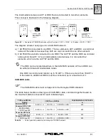
Read the static pressure value of the network on the pressure gauge and check that
it is within the required pressure limits (see "GAS SUPPLY SYSTEM” on page 47).
5.
Close the gas supply valve.
6.
Disconnect the pressure gauge and replace the seal screw of the gas pressure jack.
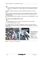
To adjust the gas flow on the ACF:
1.
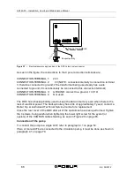
With the gas valve closed, loosen the sealing screw on the gas pressure outflow
jack, letter C in Figure 37 on page 76.
2.
Connect the pressure gauge to the gas pressure outflow jack.
3.
Open the gas supply valve and turn on the ACF.
4.
Start-up the ACF using the control switch commands (on/off, programming clock,
etc.) or by means of the Direct Digital Controller(if present).
5.
Wait for the burner to ignite. If it doesn't ignite at the first attempt, the flame control
unit will make another 3 attempts. If the burner does not ignite after the fourth
attempt, the flame control unit will arrest. In this situation, the flame control unit must
be reset by following the indications given in paragraph 2.4 on page 35 (or through
the Direct Digital Controllerif present) until the burner ignites.
6.
After the burner is lit, check that the pressure shown on the pressure gauge is in
conformance with that reported in Table 25 on page 75.
7.
If the gas pressure need to be adjusted, keep the burner on and the pressure gauge
connected, turn, (raising the upper part of the left lateral panel and previously
removing the protective plug), screw A on the gas valve (letter A in Figure 37 on
page 76), turning it clockwise to increase the pressure and counter clockwise to
reduce it, until obtaining the pressure indicated in Table 25 on page 75; when the
operation is finished, replace the protective plug for screw A.
8.
Shut down the ACF through the control switch commands (on/off, programming
clock, etc.) or by means of the Direct Digital Controller(if present).
9.
Close the gas supply valve.
10. Disconnect the pressure gauge and replace the seal screw of the gas pressure jack
C on Figure 37, page 76.
11. Open the gas supply valve.
12. Use a soap solution to check for any leaks coming from the gas connections.
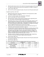
TYPE OF GAS
NATURAL GAS
(G20)
LPG (G30)
LPG (G31)
PRESSURE AT THE BURNER
6.2 mbar
11.1 mbar
14.0 mbar
AIR DIAPHRAGM
31.5 mm;
29.8 mm;
29.8 mm;
NOZZLE DIAMETERS
5.3 mm;
3.3 mm;
3.3 mm;
Table 25 –
Gas pressure at the burner, air diaphragm and nozzle diameters.
Содержание GA ACF60-00
Страница 4: ......
Страница 6: ...ACF60 00 Installation User s and Maintenance Manual 2 Ed 04 2012 ...
Страница 56: ...ACF60 00 Installation User s and Maintenance Manual 52 Ed 04 2012 ...
Страница 86: ...ACF60 00 Installation User s and Maintenance Manual 82 Ed 04 2012 ...
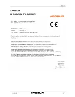
Страница 91: ...APPENDIX Ed 04 2012 87 APPENDIX DECLARATION OF CONFORMITY ...
Страница 92: ...ACF60 00 Installation User s and Maintenance Manual 88 Ed 04 2012 ...
Страница 93: ...APPENDIX Ed 04 2012 89 ...
Страница 94: ...ACF60 00 Installation User s and Maintenance Manual 90 Ed 04 2012 ...
Страница 95: ......


