Section ELECTRICAL INSTALLER
Ed. 04/2012
63
Before working on the electric panel of the ACF, ensure that the electrical power
supply is disconnected.
1.
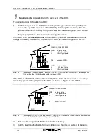
Remove the front panel of the ACF and the cover of the electrical panel.
2.
Cut the ideal length of cable for the installation so that it will not undergo bending.
3.
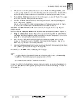
Having chosen one end of the length of cable, remove the sheath from a length of
approximately 70-80 mm, taking care not to cut the shielding (metallic shield and/or
aluminium sheet and, if present, the bare connector in contact with the shield) and
the wires contained within.
4.
If the diameter of the cable used is not large enough to be blocked inside the cable
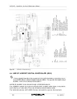
clamp (letter C of Figure 26 on page 62), make it larger by wrapping electrical tape
over the protective outer covering in the area adjacent to the unsheathed part
(approximate diameter required: 12-13 mm).
5.
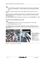
Pull back the shielding in the sheathe; apply electrician’s tape to the end of the
shielding as pulled back (letter A of Figure 26, page 62).
6.
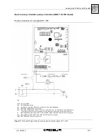
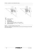
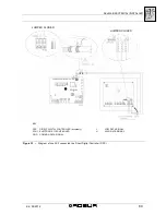
If the appliance is a
terminal node
of the network connect the three coloured wires
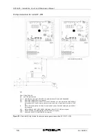
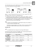
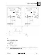
to the orange connector, as shown in detail A; of Figure 27 on page 64. Respect the
correct indications L, H, GND provided in Table 24 on page 61, on the figure and on
the diagram at the base of the connector.
7.
If the appliance is an
intermediate node
repeat the operations from step 3 to step 6
for the other length of cable required (so to will have two cable lengths everyone
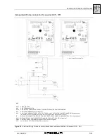
without the sheath). To interlace between they the threads with the same color and
to connect them to the orange connector, as shown in detail B; of Figure 27 on page
64.
8.
Fix the CAN bus cable (or two cables, according to the type of node being
connected) to the cable fixing bracket in the upper part of the inside of the electrical
panel so that the rolled-back sheathing makes solid contact with the metal bracket.
The cables must be held firmly in place by the bracket if pulled..
Requirements:
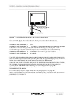
Access to the electronic circuit board.
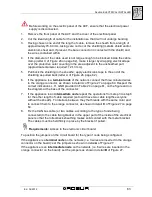
To position the jumpers on the circuit board for the type of node being configured:
If the appliance is a
terminal node
on the network (i.e. 3 wires are inserted in the orange
connector on the board): set the jumpers as shown in detail
A
of Figure 27.
If the appliance is an
intermediate node
on the network (i.e. 6 wires are inserted in the
orange connector on the board); set the jumpers as shown in detail
B
of Figure 27.
Содержание GA ACF60-00
Страница 4: ......
Страница 6: ...ACF60 00 Installation User s and Maintenance Manual 2 Ed 04 2012 ...
Страница 56: ...ACF60 00 Installation User s and Maintenance Manual 52 Ed 04 2012 ...
Страница 86: ...ACF60 00 Installation User s and Maintenance Manual 82 Ed 04 2012 ...
Страница 91: ...APPENDIX Ed 04 2012 87 APPENDIX DECLARATION OF CONFORMITY ...
Страница 92: ...ACF60 00 Installation User s and Maintenance Manual 88 Ed 04 2012 ...
Страница 93: ...APPENDIX Ed 04 2012 89 ...
Страница 94: ...ACF60 00 Installation User s and Maintenance Manual 90 Ed 04 2012 ...
Страница 95: ......


