ACF60-00 – Installation, User’s and Maintenance Manual
54
Ed. 04/2012
ACF Hook-up
Requirements:
The ACF must be positioned in its final location.
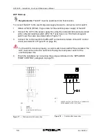
To connect the ACF to the electrical power supply line and to connect a control switch:
1.
Obtain a FG7(O)R 3Gx1,5 type cable for the electrical power supply of the ACF.
2.
Connect the ACF to the power supply line using the indicated cable and also install
either a bipolar isolating switch with 2 5A T-type fuses or a 10A thermomagnetic
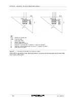
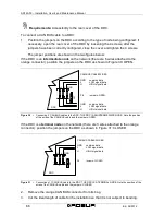
switch near the cable (see detail GS on Figure 17).
3.
Connect the control switch to the
R
and
Y
connection terminals of the ACF control
circuit (see detail IC of Figure 18 on page 54).
For the ACF to function properly, a control switch must ALWAYS be installed. The
ACF must not be turned on and shut off using the main power switch of the
electrical power line.
4.
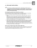
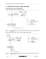
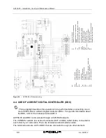
Finish the installation by connecting the pump as indicated in the “APPLIANCE
PUMP CONTROL” paragraph on page 55.
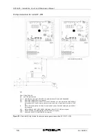
Figure 17 –
Main power switch connection
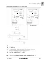
Figure 18 –
Control switch connection
KEY
L
PHASE
N
NEUTRAL
GS
MAIN POWER SWITCH (not
supplied
KEY
IC
CONTROL SWITCH (ON-OFF SWITCH, THERMOSTAT,
PROGRAMMING CLOCK, OR OTHER)
Содержание GA ACF60-00
Страница 4: ......
Страница 6: ...ACF60 00 Installation User s and Maintenance Manual 2 Ed 04 2012 ...
Страница 56: ...ACF60 00 Installation User s and Maintenance Manual 52 Ed 04 2012 ...
Страница 86: ...ACF60 00 Installation User s and Maintenance Manual 82 Ed 04 2012 ...
Страница 91: ...APPENDIX Ed 04 2012 87 APPENDIX DECLARATION OF CONFORMITY ...
Страница 92: ...ACF60 00 Installation User s and Maintenance Manual 88 Ed 04 2012 ...
Страница 93: ...APPENDIX Ed 04 2012 89 ...
Страница 94: ...ACF60 00 Installation User s and Maintenance Manual 90 Ed 04 2012 ...
Страница 95: ......


