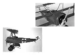
ROBBE 2572 Скачать руководство пользователя страница 3

Fokker DR 1 ARF

3

Specification

Wingspan: 

approx. 1320 mm

Overall length: 

approx. 1020 mm

Total surface area: 

approx. 33 dm2

All-up weight: 

approx. 1500 g

Total surface area loading: 

approx. 46 g/dm2

See separate sheet for list of essential items not included in the kit


Please refer to the main robbe catalogue for further details of 

battery chargers, tools and aids to building

Dear Customer,

Congratulations on your choice of a factory-assembled model air-

craft from the robbe Modellsport range. Many thanks for placing 

your trust in us.

Sequence of assembly

Please study the illustrations and the brief instructions to obtain a 

clear understanding of the individual stages of construction.

The model can very quickly be completed, ready to fly. Please read 

right through these instructions, the separate information sheets and 

the Safety Notes before attempting to assemble and fly the model, 

as this will make it much easier to complete the tasks required.

We constantly strive to update our products to reflect the latest 

developments. 

You can find details of technical improvements, 

updates and revised documentation on the Internet by calling 

up the appropriate product description at our website: www.

robbe.com.

All directions, such as “right-hand”, are as seen from the tail of 

the model, looking forward.

Notes regarding the radio control system

For this model you require a computer radio control system with 

at least six channels. This will enable you to adjust control surface 

travels, servo neutrals, servo direction and Expo at the transmitter.

We particularly recommend 2.4 GHz systems.

Separate servos are employed to actuate the two ailerons.

The receiving system is powered by the speed controller’s integral 

BEC system.

Before you start construction, ensure that your receiving system 

components will fit in the model where shown. 

If you intend to install system components other than those we 

recommend, you can still follow the same basic arrangement. You 

may need to make minor adjustments to compensate for differences 

in component sizes.

Set the servos to neutral from the transmitter (transmitter sticks and 

trims central) before installing them. 

Remove any output discs or levers from the servos.

Before flying the model always move the throttle stick to the “motor 

stopped” position before switching the transmitter on. Only then 

connect the flight battery.

To switch off, first disconnect the flight pack from the speed control-

ler, and only then switch the transmitter off.

When installing or setting up the receiving system componen-

ts, including the speed controller and motor, be sure to read 

and observe the instructions supplied with them.

You should also read right through the instructions and safety 

information supplied with the battery pack and charger before 

using these items for the first time.

Glued joints

All parts must be trial-fitted “dry” (without glue) before you reach for 

the adhesive.

Use abrasive paper to roughen all joint surfaces before applying 

glue.

The text states which adhesive - epoxy, white glue, cyano - is 

required for particular joints.

Notes on covering

Temperature fluctuations in transit may result in partial loss of ten-

sion in the covering film.

The film will become taut again if you play warm air from a heat-gun 

over the slack area, and rub the film down smooth.

Servo wells, attachment points, hinge slots and holes are concealed 

by the covering film. You can locate them by feel with your finger-

tips, and remove the covering film over them.

At a few areas the film covering has to be removed at joint areas; 

take care not to score the underlying wood when you do this. We 

recommend that you use a small soldering iron, and melt away the 

film with the hot tip.

Painting the model, applying the decals

The model is supplied with the decals already applied. No painting 

is required.

Take care that the decals do not come into contact with adhesive 

(cyano), as this may damage the surface. 

If you are aiming at a more realistic finish, a 

„weathering set“

 is 

available which enables you to age the surfaces artificially.

Replacement parts 

Order No. 

Description


25720001  

Fokker fuselage set

25720002  

Fokker dummy engine and machine gun

25720003  

Fokker main undercarriage set

25720004  

Fokker wing set  

25720005  

Wing rigging set 

25720006  

Fokker tail set    

25720007  

Fokker cowl   

25720008  

Fokker wheels               

25720009  

Fokker tailskid       

Tail set

Note: 

the control surfaces are actuated by means of braided wire 

pull-cables; the elevators are actuated by four pull-cables. Assign 

the cables to the individual linkages, and cut them overlength.

Figs. 1 and 2

-  Thread the two short pull-cables „SR“ (rudder) through the two 

slots in the tail end of the fuselage. Four slots are also present for 

the four longer pull-cables „HR“ (elevator).

-  Group the braided wires together with tape and secure them 

temporarily.

-  Place the tailplane on the fuselage, centre it accurately, and fix it 

temporarily. 

Fig. 3

-  Attach the elevators to the tailplane by gluing the hinges in the 

slots. You can either use cyano-acrylate („cyano“) or white glue 

for this.

Fig. 4

-  Glue the tailplane to the fuselage using white glue (PVA). Check by 

eye that the tailplane is exactly horizontal and accurately centred. 

-  Install the rudder by gluing the hinges in the slots. Check that it is 

exactly at right-angles to the tailplane. 

Figs. 5 and 6

-  Remove the covering film over the horn slots. Glue the horns in 

the elevators and rudder using cyano or white glue.

Figs. 7 and 8

-  The hatches on the underside of the fuselage are held in place by 

locating tongues at the front and magnets at the rear. Raise the 

rear of the hatches and lift them off. 

Assembly and operating instructions

© robbe Modellsport

No.


2572

Содержание 2572

Страница 1: ...Assembly and operating instructions Notice de montage et de pilotage Istruzioni di montaggio e d uso Instrucciones de Construcción y de Uso Stavební a provozní návod Fokker DR 1 ARF No 2572 ...

Страница 2: ...2 ...

Страница 3: ...upplied with the battery pack and charger before using these items for the first time Glued joints All parts must be trial fitted dry without glue before you reach for the adhesive Use abrasive paper to roughen all joint surfaces before applying glue The text states which adhesive epoxy white glue cyano is required for particular joints Notes on covering Temperature fluctuations in transit may res...

Страница 4: ... and glue the skid to the fuselage Bottom wings undercarriage Fig 15 Main undercarriage struts and components V front struts each with four holes H rear struts each with two holes Fig 16 Insert the joiner tube 8 x 284 mm in one of the bottom wing panels Figs 17 19 Slide both bottom wing panels onto the joiner tube until they rest against the fuselage Install the rear undercarriage struts and screw...

Страница 5: ...he front wing struts and secure them with adhesive tape Tighten all the screws in the wing struts Fig 42 Slot together the dummy machine guns and the cockpit wind screen Glue this assembly to the top fuselage decking Figs 43 and 44 Place the top decking on the fuselage and align it accurately Attach the rear end of the top decking using two 2 Ø x 6 self tapping screws as shown ensure that the deck...

Страница 6: ...er must turn anti clockwise when viewed from the front If this is not the case swap over any two of the three wires bet ween the motor and the speed controller First disconnect the flight battery from the speed controller then switch the transmitter off Fig 62 balancing Mark the Centre of Gravity C G on both sides of the fuselage at a point 87 mm from the leading edge of the top wing Support the m...

Страница 7: ...n position Moteur arrêt mettre l émetteur en marche Raccorder d abord l accu Pour couper l ensemble de radiocommande désolidariser d abord la connexion entre l accu et le moteur en suite coupe l émetteur Pour tous travaux sur les éléments de l ensemble de radiocom mande du moteur et du variateur tenir compte des indications fournies par les notices qui les accompagnent Lisez attentivement les inst...

Страница 8: ...ez les chapes Veillez à leur liberté de mouvement dans le plan fixe Fig 13 et 14 Raccordez les chapes restantes aux guignols Tirez sur les torons et agencez les de la sorte Raccordez les torons et fixez les avec une cosse à écraser Mettez l étai en place et collez à l extérieur dans les alésages à l intérieur fixez avec une vis autotaraudeuse Ø 2 2 x 12 Retirez le film de protection et collez la b...

Страница 9: ...ez à fond toutes les vis des étais des ailes Fig 42 Assemblez les mitrailleuses factices et le pare brise du cockpit Collez l unité sur le capot du fuselage Fig 43 et 44 Installez le capot du fuselage sur le fuselage et alignez le La capot est fixé à l arrière par 2 vis autotaraudeuses Ø 2 x 6 Ce faisant veillez à ce que le capot s engage proprement dans les gorges dans le secteur du plan fixe hor...

Страница 10: ...se des aiguilles d une montre Si ce n est pas le cas intervertissez deux des trois brins de liaison entre le moteur et le variateur Désolidariser d abord la liaison accu variateur avant de cou per l émetteur Fig 62 équilibrage Repérez le centre de gravité C G bilatéralement sur le fuselage à une distance de 87 mm du bord d attaque Calez le modèle au niveau de son centre de gravité et laissez le en...

Страница 11: ...elative all apparecchio Prima della messa in funzione leggere attentamente le istruzi oni dell accumulatore e del caricabatterie Lavori di incollaggio Adattare prima a secco tutti i componenti prima di incollarli Sfregare con carta vetrata tutte le superfici da incollare Nel testo vengono indicati i diversi incollanti colla legno colla istantanea Indicazioni per il rivestimento Cambiamenti di temp...

Страница 12: ...drette timone Tirare i cavetti e assegnarli Collegare i cavetti e fissarli con un manicotto appiattito Posare il sostegno e incollare esternamente nei fori internamente fissare con una vite autofilettante Ø 2 2 x 12 Rimuovere la pellicola incollare il ruotino di coda Superfici portanti e carrello inferiori Figura 15 Montanti e componenti del carrello principale A Montanti anteriori ognuno con quat...

Страница 13: ...e Figura 41 Portare la struttura di tensione a croce tra i montanti anteriori della superficie come descritto per il carrello Condurre il cavo del servo dei servi dell alettone lungo i montanti anteriori delle superfici portanti verso il basso alla fusoliera e assi curare con nastro adesivo Stringere tutte le viti dei montanti delle superfici portanti Figura 42 Montare insieme la mitragliatrice fi...

Страница 14: ...nonché all avvio non entrare mai in contatto con l area di rotazione delle eliche pericolo di ferita Verificare il senso di rotazione del motore Il motore visto dal davanti deve girare in senso antiorario Se ciò non dovesse accadere invertire due dei tre cavi di collega mento tra motore e regolatore Innanzitutto dividere il collegamento accumulatore regola tore poi spegnere la trasmittente Figura ...

Страница 15: ...l motor o del regulador siga siempre las instrucciones adjuntas a cada uno de los aparatos Lea también atentamente las instrucciones de la batería y del cargador antes de la puesta en funcionamiento Trabajos de encolado Antes de encolar las piezas ajústelas siempre previamente en seco Lije todos los puntos a encolar con papel de lija En el texto se indican los diferentes adhesivos a utilizar cola ...

Страница 16: ...12 Retirar el film y encolar el patín de cola Parte inferior de las alas y tren de aterrizaje Foto 15 Tirantes y piezas individuales del tren de aterrizaje principal V Tirantes delanteros con 4 perforaciones cada uno H Tirantes traseros con dos perforacionescada uno Foto 16 Introducir la pieza de unión tubo 8 x 284 mm en una de las alas inferiores Fotos 17 19 Posicionar las dos alas inferiores med...

Страница 17: ...ara los servos de los alerones siguiente las riostras delanteras de las alas hacía abajo dentro del fuselaje y asegurarlos con celo Apretar todos los tornillos de las riostras de las alas Foto 42 Ensamblar los simuladores de las ametralladoras y el disco del cockpit Encolar la unidad sobre la tapa del fuselaje Fotos 43 y 44 Posicionar la tapa del fuselaje sobre el fuselaje y alinearla Fijar la tap...

Страница 18: ...acción de la hélice riesgo de lesiones Verificar el sentido de giro del motor Visto desde delante el motor debe girar en sentido horario Si no fuera asi cambiar dos de los tres cables de conexión entre motor y variador Separar siempre primero la unión batería variador entonces apagar la emisora Foto 62 equilibrado Marcar el centro de gravedad C G en ambos lados del fuselaje a 87 mm del borde de at...

Страница 19: ...h dálkového řízení motoru nebo regulátoru vždy dbejte pokynů uvedených v přiložených návodech přístrojů Rovněž si před uvedením do provozu pozorně přečtěte bezpečnostní pokyny k akumulátorům a nabíječům Lepení Před lepením zkuste díly vždy napřed zkompletovat nasucho Všechna lepená místa zdrsněte brusným papírem Na jiná lepidla jako disperzní lepidlo vteřinové lepidlo je poukázáno v textu Pokyny p...

Страница 20: ...kormidel ocasních ploch Obr 13 a 14 Ostatní vidličky připojit k ovládacím pákám kormidel Potahováním za licny se určí jejich příslušnost Licny připojit a pojistit mačkacím pouzdrem Nasadit opěru a přilepit z vnějšku do otvorů zevnitř připevnit samořezným šroubem Ø 2 2 x 12 Odstranit fólií a zalepit ostruhu Spodní křídlo a podvozek Obr 15 Vzpěry a jednotlivé díly hlavního podvozku V Přední vzpěry v...

Страница 21: ...Hotové horní křídlo nasadit Vzpěry přimontovat k držákum středního křídla šrouby M 2 x 10 podložky a matice M 2 Obr 40 4 vnitřní vzpěry křídla přišroubovat vždy přišrouvovat 2 ohnutá závěsná ložiskaek nahoře současně s předními vzpěrami Obr 41 Zhotovit křížové vyztužení mezi předními vzpěrami křídel tak jak již bylo popsáno u podvozku Kabely serv křidélek zavést podél předních výztuh křídel směrem...

Страница 22: ...tří přípojovacích kablů mezi motorem a regulátorem Napřed rozpojit spojení mezi letovým aku a regulátorem pak teprve vypnout vysílač Obr 62 vyvážení Polohu těžiště C G označte na obou stranách trupu ve vzdále nosti 87 mm od horní náběžné hrany Model podepřít v těžišti C G a nechat jej vyvážit Ideální polohy těžiště je dosaženo když model zůstane v rovnováze s lehce dolů nakloněnou přídí trupu Poku...

Страница 23: ...23 robbe Modellsport ...

Страница 24: ...robbe Modellsport GmbH Co KG Metzloser Str 38 Telefon 06644 87 0 D36355 Grebenhain www robbe com robbe Form ABBC ...

Отзывы: