[6 - 14]
CHAPTER 6. PAPER DRUM SECTION
Assembling back the gripper shaft unit
(1)
Fit the gripper shaft unit back on the paper drum.
(2)
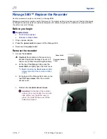
Mount the gripper gear on the machine rear side of the griper shaft unit.
The groove on the gripper gear should face outside.
(3)
Mount the gripper cover shaft, together with the metal bearings on the front and rear.
The side with stepped down diameter should be for the rear side.
(4)
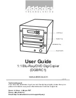
Fix the gripper shaft reinforcing arm in position by two screws.
The top surface of the reinforcing arm should be flat with the reinforcing base, as shown
by “A” on the sketch below. The surface indicated by “B” on the sketch should also align
with each other, though may need to slide the reinforcing arm a little bit to allow smooth
movement of the gripper shaft unit and gripper cover shaft.
(5)
The final position of the gripper shaft will be readjusted, if required, after running B4 size thin
papers or recycled papers. If paper wrinkle appears, especially on the tail end of the paper, the
gripper shaft reinforcing arm will need to be moved in the direction shown by the arrow mark
indicated under the alphabet “
B
” on the sketch.
P0632
S0633
Gripper gear
Gripper shaft reinforcing arm
Gripper shaft unit
Gripper shaft reinforcing base
Gripper cover shaft
(groove on the Gripper gear)
B
A
Содержание V8000 Series
Страница 30: ... 1 19 CHAPTER 1 MAINTENANCE 4 Removing Exterior Covers Rear cover Rear cover P0112 ...
Страница 31: ... 1 20 CHAPTER 1 MAINTENANCE Front doors L R Front door R Front door L P0113 P0114 P0115 P0116 ...
Страница 42: ... 2 6 CHAPTER 2 MACHINE OVERVIEW MEMO ...
Страница 54: ... 3 12 CHAPTER 3 MAIN DRIVE SECTION MEMO ...
Страница 78: ... 4 24 CHAPTER 4 FIRST PAPER FEED SECTION MEMO ...
Страница 92: ... 5 14 CHAPTER 5 SECOND PAPER FEED SECTION MEMO ...
Страница 105: ... 6 13 CHAPTER 6 PAPER DRUM SECTION Gripper shaft unit Gripper collar P0630 P0631 REAR Gripper shaft unit FRONT ...
Страница 112: ... 6 20 CHAPTER 6 PAPER DRUM SECTION MEMO ...
Страница 133: ... 8 7 CHAPTER 8 PRINT DRUM SECTION Hanger E Clamp plate base ass y P08006 P08007 Screen ass y Hanger TA ...
Страница 141: ... 8 15 CHAPTER 8 PRINT DRUM SECTION Pressure control motor ass y P08028 P08029 Pressure control motor ass y Connector ...
Страница 170: ... 8 44 CHAPTER 8 PRINT DRUM SECTION MEMO ...
Страница 178: ... 9 8 CHAPTER 9 VERTICAL PRINT POSITION SECTION MEMO ...
Страница 206: ... 11 20 CHAPTER 11 MASTER DISPOSAL SECTION MEMO ...
Страница 209: ... 12 3 CHAPTER 12 FB ORIGINAL SCANNING SECTION MEMO ...
Страница 263: ... 15 1 CHAPTER 15 TIMING CHARTS Contents This chapter is not completed ...
Страница 333: ... 18 4 CHAPTER 18 FUNCTIONS MEMO ...
Страница 355: ... 20 18 CHAPTER 20 PRINTED CIRCUIT BOARDS MEMO ...