background image

19

2 INSTALLATION 

GUIDE

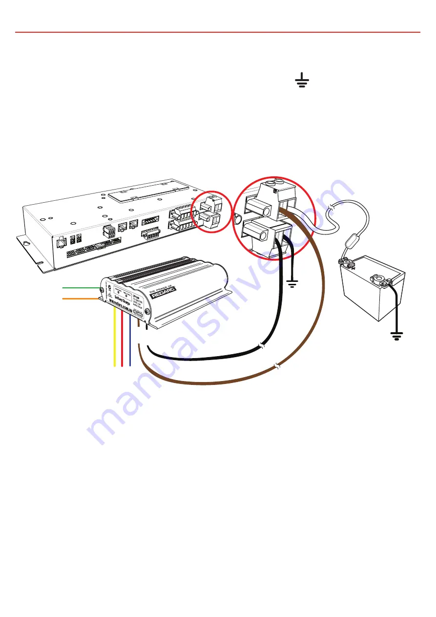
2.6.3  Charger Connection (BCDC)

The BCDC should be mounted as close as possible to the Distribution Box. Connect 
the BCDC’s battery output positive (+) and Ground (

) to the Distribution Box 

Charger (+) and Ground (-) connections. 
Refer to Section 2.3 for cable sizing.

The Distribution Box includes a 50A MIDI fuse to protect the charging circuit (the 
maximum charging current is 40A). Refer to Section 2.5 for details.

Auxiliary Battery

Supplied

Fuse

Black

Bro

wn

Содержание Redvision TVMS1280

Страница 1: ...Total Vehicle Management System TVMS1280 ...

Страница 2: ...rience and knowledge unless they are supervised or have been instructed on how to use the appliance by a person responsible for their safety Children should be supervised to ensure that they do not play with the system 3 Do NOT alter or disassemble the system under any circumstances All services or repairs must be returned to REDARC for repair Incorrect handling or reassembly may result in a risk ...

Страница 3: ...f damage to the system Do NOT connect to the TRC socket at the front 240V end of the inverter as this will cause damage to the RedVision Distribution Box Connect to the REMOTE socket to avoid damage 1 Do NOT connect computers or IT equipment to the RJ45 ports on the RedVision Distribution Box or Display Damage may occur 2 It is recommended to leave the Display connected at all times to the base un...

Страница 4: ...s Connection 21 2 9 Water Level Sensors 23 2 10 Optional Inverter Connection 24 3 System Configuration 25 3 1 RedVision Configurator App 25 3 2 Configure Charger 26 3 3 Configure Battery Sensor 26 3 4 Configure Distribution Box Load Disconnect Settings 27 3 5 Configure Distribution Box Channels 28 3 6 Configure Display Soft Keys 31 3 7 Configure Display Home Screen 32 3 8 Configure Display Status ...

Страница 5: ... quality OEM Benefits of RedVision Feature expandability for vehicle customisation to customer order Easily up sell value add components such as inverters Decreased installation time and complexity Reduced weight and area of components Improved service and support Packaged pricing and delivery Decreased production time Features Read up to two temperatures Read up to six water tanks View and contro...

Страница 6: ...i fuse 1 Midi fuse holder 2 50A midi fuses fitted 4 Crimp terminals for fuse holder 1 0 5m R Bus Cable 1 3m Inverter Remote Cable 1 R Bus Terminator 2 Temperature Sensors 6 Power cable mating connectors 1 Digital I O mating connector Display DISP4300 Qty Part 1 4 3 Display 1 Optional Mounting Spacer 1 Display Fascia 1 R Bus Terminator 1 5m R Bus Cable ...

Страница 7: ...ght 2 0kg 0 3kg Warranty 2 years Electrical Specifications System Voltage 12V Maximum Charger Current 40A Maximum Battery Current 80A No Switched Circuits 5 x 10A Max 5 x 30A Max 1 3 Compatible Devices Type REDARC Part Number Device Connection Wire Relevant section of this manual Chargers BCDC1220 N A Section 2 6 BCDC1220 IGN BCDC1225D BCDC1240D Battery Management Systems BMS1215S3 CAN R BUS Secti...

Страница 8: ...7 1 INTRODUCTION 1 4 Dimensions 27mm 2 5mm 58mm 66mm 28mm Ø6mm 138mm 80mm 71 5mm Ø6mm Ø11mm 385mm 370mm 350mm Figure 1 4 1 Distribution Box Dimensions ...

Страница 9: ...8 1 INTRODUCTION Figure 1 4 2 Display Dimensions 107 5mm 18 5mm 11mm 7mm 178mm 6mm 156mm 158mm 19mm 15mm 25 5mm 39mm Ø 4 5 m m X 4 91mm 6mm 96mm 103mm 11mm Optional Spacer ...

Страница 10: ...those that could cause harm if operated remotely for example fume exhaust fans or lifters Auxiliary Battery Water Level Sensors Temperature Sensors Distribution Box Display To Alternate Trigger Signals To Ignition Small Loads Large Loads BMS T Piece Terminating Resistor Inverter Battery Sensor Fuse Fuse ...

Страница 11: ...stribution Box The Distribution Box may be mounted in any orientation but must be mounted onto a flat solid surface using 4 x M6 screws or bolts Failure to adequately mount the unit such as using adhesives to mount the unit may result in unreliable operation of the Distribution Box Ensure clear access to the fuse panel to ensure service of fuses and override of channels can be performed 15 30 4 x ...

Страница 12: ...environments such as being exposed to rain or severe amounts of dust or full time direct sunlight Ensure that the Display is not mounted in vehicle head impact zones Doing so may result in injury to the driver and or passenger in the event of an accident Ensure the Display is not mounted where it may distract the driver of the vehicle Distracting the driver may result in an accident Spacer optiona...

Страница 13: ...12 2 INSTALLATION GUIDE 2 2 3 Removing the Display Fascia ...

Страница 14: ...out template 2 2 4 Flush Mount Drill Cut Dimensions 2 2 5 Surface Mount Drill Cut Dimensions 91 156 164 101 109 132 58 35 45 91 156 Ø45mm 24 46 NOT TO SCALE Refer to page 48 for a 1 1 cutout template NOT TO SCALE Refer to page 48 for a 1 1 cutout template ...

Страница 15: ... length 3M Cable Length 3M Charger Output Ground 16 mm 4B S 8B S 6B S Auxiliary Battery Positive Ground 16 mm 4B S 6B S 4B S 2 3 2 Output Wire Diameter Selection REDARC recommends the installer use suitably rated cable and fuses for the load connected Refer to the table below for the 10 and 30 amp connector terminal sizes and maximum cable sizes Connection Terminal Size Max Cable Size 10A Circuits...

Страница 16: ...output loads on off when triggered for example to turn off all loads except a fridge when the vehicle ignition is on The Start Battery Positive and Start Battery Negative inputs can be used to monitor and display a voltage from an external source for example to display the vehicle s starter battery voltage Start Battery Positive Start Battery Negative 1 2 3 Digital Inputs ...

Страница 17: ...rents inductive type loads e g large fridges pumps motors should be connected through the 30A Max circuits 2 5 2 Load Negatives Wire each load positive and negative to the applicable output channel Alternatively load negatives may be connected at a suitable chassis grounding point Risk of damage to the system Do NOT connect a load negative to the chassis AND to the applicable negative output chann...

Страница 18: ... 2 5 4 Override Switches Under normal conditions each load output channel may be switched using the display however should a load need to be manually switched on the override switches located between the two fuse banks may be used Overriding is a two stage process firstly override mode must be enabled using the master override switch located to the left of the two switch banks The master override ...

Страница 19: ...r earth stud or connect directly to the GND terminal of the Manager s battery sensor 2 6 2 Charger Connection Manager 15 or 30 The Manager should be mounted as close as possible to the Distribution Box Connect the Battery Management System s battery output positive and Ground to the Distribution Box Charger and Ground connections Refer to Section 2 3 for cable sizing The Distribution Box includes ...

Страница 20: ...ct the BCDC s battery output positive and Ground to the Distribution Box Charger and Ground connections Refer to Section 2 3 for cable sizing The Distribution Box includes a 50A MIDI fuse to protect the charging circuit the maximum charging current is 40A Refer to Section 2 5 for details Auxiliary Battery Supplied Fuse Black Brown ...

Страница 21: ...to the system by simply plugging into the two sockets on the Distribution Box Additionally the REDARC sensors in the table below are also compatible Part Number Material Sensing Range Application Mounting Size GS UT 80 ABS Plastic 20 to 80 C Fridges Freezers Cabin Ambient etc N A GS UT 120 Copper 20 to 120 C 6mm Hole For further information about REDARC sensors visit http redarcqr com gaugesensors...

Страница 22: ...n Box 2 Use the 5 metre RJ45 cable to connect the remaining socket on the Distribution Box to the Display 3 Fit the Terminating Resistor to the remaining socket in the Display 4 When a Manager 15 or 30 is used the terminating resistor for the other end of the Bus is inbuilt in the BMS If a Manager 15 or 30 is not used the supplied terminating resistor should be inserted into one of the ports on th...

Страница 23: ...oving the need to add an extra terminating resistor to one end of the system The other end of the network should be terminated by inserting the supplied Terminating Resistor into the last device in the network for example into the RedVision Display in the diagram on page 22 If no Manager 15 or 30 is used insert the supplied terminating resistors into both the Display and the Distribution Box CAN D...

Страница 24: ...ctronics SP0004 SP0011 SP0028 To use simply connect the sender directly to the distribution box inputs Other 2 5 pin tank senders Alternatively most 2 5 pin conductive tank sensors can be used in conjunction with an AMP 171822 5 connector not supplied To use wire as shown below noting that colours may vary refer to the manufacturer s specification sheet Wire 5 if applicable Wire 4 if applicable Wi...

Страница 25: ...cluding fuse and cable sizing Risk of damage to the system Do NOT connect to the TRC socket at the front 240V end of the inverter as this will cause damage to the RedVision system Connect to the REMOTE socket to avoid damage 1 Connect the non overmoulded end of the supplied RJ12 cable to the REMOTE socket at the Rear 12V end of the inverter 2 Connect the over moulded end of the supplied RJ12 cable...

Страница 26: ... successfully paired the App will download your current system configuration save it and then you should see the RedVision Configurator Main Menu The App has now downloaded your RedVision system settings which you can now change 2 Alternatively you may choose Open Configuration to open a previously saved configuration Tapping this button will take you to the Choose Configuration screen 3 From this...

Страница 27: ...rm settings 3 3 Configure Battery Sensor The Configure Battery Sensor page allows you to set the Battery Type Size and Maximum Charge Current along with SoC Voltage alarm levels The default battery type is Gel The default battery size is 40AH The default Maximum Charge Current is the maximum output of your Manager 15A 30A The default SOC Alarm is 10 The default Voltage Alarm is 10 5V For more info...

Страница 28: ...e at the Batt terminal on the Distribution Box BMSVoltage Triggers on voltage of theAuxiliary Battery as measured by the Manager BMS SoC Triggers on SoC of the Auxiliary Battery as measured by the Manager Never Always Connected Next the Disconnect and Reconnect levels must be set based on the method selected The App will ensure that Disconnect is always set 5 or 0 5V lower than Reconnect depending...

Страница 29: ...se these inputs for vehicle ignition and reverse signals for example which will allow certain outputs to be turned ON or OFF automatically Outputs These are the 5x 30A and 5x 10A channels which you can control from the RedVision App and Screen Inverter This channel controls an Inverter connected to the Optional Inverter Connection on the RedVision Distribution Box Sensors These control the 2x Volt...

Страница 30: ...er or Over Alarms to trigger based on the Input Measurement These may be Voltage Temperature or Water Tank Level 4 Tank Settings Allows definition of the Water Tank Level sensing device including the type of probe used and the water type stored in the tank i e Clean Black Brown etc 5 Inverter Settings Allows enabling of Inverter communications settings should a REDARC RS series inverter be connect...

Страница 31: ... or Input Override can be selected The channel will default to have both of these turned OFF ON only during button press Allows the channel to only be active while the button Soft Key is depressed This may be used for raising or lowering steps or an awning Input Override Allows the channel to be locked ON or OFF by a Digital Input as well as via User Control Digital Input Control In either Input C...

Страница 32: ... created and configured by tapping the button at the bottom of this page Tap SAVE to confirm settings 3 6 1 Soft Key Configuration To add a new channel to a Soft Key simply tap on the empty slot then tap Choose A list of all available channels will appear Scroll up down as necessary and tap on the channel you want to be in that position Tap SAVE to confirm settings From the Configure Soft Keys Men...

Страница 33: ...ill appear on the right Inverter Channel This drop down menu allows you to select the Inverter channel to be displayed Ensure Enable Communications is selected Refer Section 3 5 1 NOTE when a home page with Inverter display is selected this section will show no information if no inverter channel is selected Water Tank Channels This drop down menu allows you to select and place in order up to four ...

Страница 34: ...the bottom of the screen and choose your screen type either Distribution Box Inverter or Tanks You can name the screen and select the information you want to be displayed The tank status screen allows you to display two rows of tank levels up to four on each row If you only select two on a row they will appear larger than if three or four are selected Tap SAVE to confirm settings 2 3 From the Main...

Страница 35: ...en Settings page allows configuration of the RedVision Display Temperature Units Simply select if you would like your units displayed in Celsius or Fahrenheit and hit save Tap SAVE to confirm settings 2 From the Main Menu 1 Tap the Display Button then 2 Tap the Temperature Units Button 1 ...

Страница 36: ... 33 25 Inverter Output Power Output Voltage 235V 500W Inverter Information The Inverter Information screen provides information if a REDARC inverter is connected to the system The Output Power reading shows the instantaneous output of the inverter as a proportion of the maximum possible output The Output Voltage reading shows the instantaneous AC output voltage 2 When used with a REDARC BMS 3 When...

Страница 37: ...ignition is on 4 1 3 Power Button Function Pushing the Power Button ONCE will open a Power Button instruction dialogue and allow switching between Storage and Touring modes Pushing the Power Button TWICE will invoke the Master Switch function This function switches a defined set of devices and can be customised by the installer to user specifications HOLDING the Power Button will put the screen in...

Страница 38: ...stribution Box settings selected by Soft Key Pushing the Up Down arrows cycle through the available settings menus Pushing the top left Back Soft Key will return the user back to the Home Screen Changing Settings Once the desired Settings Screen is selected using the Soft Keys the available settings can be modified Pushing the Up Down arrows will cycle through the settings Pushing the Left Right a...

Страница 39: ...rmation on Starter and Auxiliary battery voltages temperatures and Water Tank levels Pushing the down arrow will display the level of up to 6 water level tanks if connected Pushing the down arrow again will display the inverter information screen 4 Distribution Box 14 4V 13 9V 33 25 6 5 4 3 Water Tank Levels Where there are more Water Tanks sensors connected than showing on the Distribution Box In...

Страница 40: ...tion if a REDARC inverter is connected to the system The Output Power reading shows the instantaneous output of the inverter as a proportion of the maximum possible output The Output Voltage reading shows the instantaneous AC output voltage Inverter Output Power Output Voltage 235V 500W ...

Страница 41: ...creen allows connection of the Display to a standalone device via Bluetooth This process is explained further in Section 4 3 1 This icon links to the Date and Time settings screen The user is prompted to enter date and time upon first startup however should this need to be changed it can be done in this menu This icon links to the Regional Settings menu This menu allows toggle of the Clock format ...

Страница 42: ...orage Mode will switch off all loads and set the Manager into Storage Mode should one be connected This icon links to the About Us screen This screen provides contact information for REDARC This icon links to the RBus Diagnostics screen This screen provides a serial number for each REDARC device connected to the system More information on the selected device can be found by clicking the top right ...

Страница 43: ...eration of the Manager product so it is important to ensure this is correct This icon links to the Charger Settings screen This screen allows setting of the DC input trigger on the Manager and allows modification of the Low Voltage and SoC alarm levels This icon links to the BMS Load Disconnect screen This allows for setting of the Load Disconnect feature on the Manager NOTE This feature operates ...

Страница 44: ...by the system installer This icon will return to the Home Screen This icon links to the Channel Information screen This screen provides information on the devices connected to the 22 available channels input and output on the Distribution Box Clicking the top right button will display more information This icon links to the RedVision Load Disconnect screen This screen allows setting of the Load Di...

Страница 45: ...the fuse is replaced Switching Errors In the event that a switching error is detected the relevant output channel will be turned off and the corresponding icon on the display will be shown in red After 60 seconds the channel will be turned ON again If the error has been fixed the channel will remain ON If the error is still present the channel will turn OFF again immediately While the channel is O...

Страница 46: ...h the battery information available when used with a REDARC Manager battery management system The RedVision App replicates MOST of the display and switching features of the Display The RedVision App and its interactions with the RedVision System have not been tested on all smartphones available on the market so is not guaranteed to work on all devices However the app has been designed ot work with...

Страница 47: ...nfigurator App move to step 5 5 Choose your Display from the list this should match the serial number on your Display which can be found in R Bus Diagnostics on the display 6 Read and agree to any disclaimers shown 7 Wait for passcode prompt this may pop up or show up as a notification depending on your phone 8 Enter the 6 digit code shown on Display 4 9 Your device is paired 5 Bluetooth Pairing A...

Страница 48: ...top left of the app The available paired Displays will be shown Select the one you want to connect to Three Gear Symbol 4 3 3 Connecting Multiple Devices The RedVision Display can manage multiple paired devices although only one can be connected at a time Closing the app will disconnect the device from RedVision Pairing a second device is the same as Section 4 3 1 When the RedVision App is closed ...

Страница 49: ...48 5 DISPLAY DRILL CUTOUT TEMPLATE TOP Without Spacer W i t h S p a c e r ...

Страница 50: ...49 THIS PAGE INTENTIONALLY LEFT BLANK ...

Страница 51: ...e control of Redarc 7 Warranty claims in respect of a Product must be made in writing to Redarc at the postal address or email address specified in clause 21 within the Warranty Period Such claims must include the following 7 1 details of the alleged defect or fault and the circumstances surrounding the defect or fault 7 2 evidence of the claim including photographs of the Product where the subjec...

Страница 52: ...e technical assistance please contact REDARC Electronics 23 Brodie Road North Lonsdale SA 08 8322 4848 power redarc com au www redarc com au Copyright 2018 REDARC Electronics Pty Ltd All rights reserved WARTVMS1280 UM REV5 ...

Отзывы: