


生活美好,臂不可少
http://www.realman-robotics.com
107
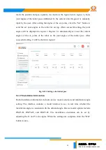
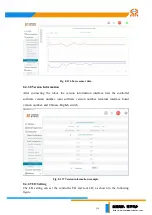
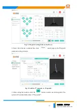
Digital Input: This section displays the status of digital I/O inputs, with gray circles
representing low inputs and green circles representing high inputs.
Digital output: This part is to configure digital I/O outputs. Press the button and the
color turns to green, and the output status of the corresponding channel is set to high.
The button turns gray when it is released, indicating that the output of the
corresponding channel is low.
Analog Input: This section displays the voltage values of the four analog I/O input
channels.
Analog output: This feature can configure the corresponding analog I/O output
channel voltage value in range of 0~10V.
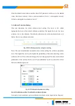
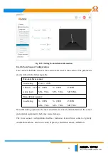
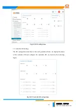
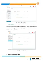
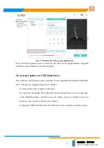
2. Tool I/O Configuration
The tool I/O interface in the teach pendant software can display the status of the tool
I/O and configure the I/O as shown in the following figure.
Fig. 8-140 Tool I/O setting demo.
Digital input/output: This part shows the status of the digital I/O. The gray circle
represents the low level, the green circle represents the high level, and the user sets


