43
METRO
PIANI DI MANUTENZIONE
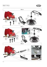
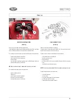
(FIG. 6 - 7- 8)
Prima di procedere alla sostituzione delle spazzole, togliere la chiave dal quadro di
avviamento, evitando così l’accensione accidentale di qualche motore e procedere nel
seguente modo.
Sostituzione spazzole a disco (fi g.6 - 7)
• smontare i portioli laterali 6 tramite la levette 7 (
fi
g. 6 e 7).
• smontare la spazzola sinistra (Fig. 7 - vale solo per macchine con tre spazzole a disco)
• sganciare la parte posteriore del basamento mediante leva 8 e s
fi
larla mediante maniglia
9 nel senso indicato in foto (Fig. 7 - vale solo per macchine con tre spazzole a disco)
• allargare la molla 2 verso l’esterno, come frecce in
fi
gura, in modo che il gruppo
spazzola 2-3-4-5 si s
fi
li dal mozzo 1 (
fi
g.6 - 7).
• svitare le viti 3 per togliere la spazzola 5 dal supporto (
fi
g.6 - 7).
Per inserire una nuova spazzola procedere nel seguente modo:
•
fi
ssare la nuova spazzola 5 sul supporto 4 con le viti 3 (
fi
g.6 - 7).
• rimontare il gruppo spazzola 2-3-4-5 sul mozzo 1 con una semplice operazione ad
incastro (
fi
g.6 - 7).
• reinserire la parte posteriore del basamento tramite maniglia 9 e bloccare con leva 8
(Fig.7 - vale solo per macchine con tre spazzole a disco).
• rimontare i portioli laterali 6 e bloccarli tramite levetta 7 (
fi
g.6 - 7).
Sostituzione spazzole a rulli (fi g.8)
procedere nel seguente modo:
1) Tirare verso l’alto la levetta laterale sinistra 1 del basamento spazzole per sganciare
il
fl
ap 2 (
fi
g.8).
2) Ruotare il supporto spazzola 3 in senso orario
fi
no a
fi
ne asola (
fi
g.8).
3) S
fi
lare il supporto 3 dal basamento e togliere la spazzola 4 sul lato sinistro come
indicato in foto (
fi
g.8).
4) Montare la nuova spazzola ripetendo le operazioni in modo inverso.
A
TTENZIONE
!
R
IMONTARE
LA
SPAZZOLA
COME
PRECEDENTEMENTE
SMONTATA
.
Per sostituire la spazzola sul lato destro bisogna rimuovere la coppiglia 5 (
fi
g.8) e
sganciare il
fl
ap 6 (
fi
g.8), quindi procedere alla sostituzione come descritto nei punti 2) 3)
4) per spazzola sinistra.
MAINTENANCE
(FIG. 6 - 7 - 8)
Before replacing the brushes, remove the key from the starter panel, to ensure that no
motor can be started accidentally, and proceed as follows:
Replacing the disc brushes (fi g.6 - 7)
• remove the side covers 6 by levers 7 (
fi
g. 6 - 7).
• unlock the rear side of the brush support by lever 8 and slide it off by handle 9 (see
arrow -
fi
g.7 only for machine with (nr.3) brushes disc type).
• extend the spring outward, as shown by the arrows in the diagram, so that the brush
assembly 2-3-4-5 comes off the hub 1 (
fi
g.6 - 7).
• unscrew the screws 3 to remove the brush 5 from the support 4. (
fi
g.6 - 7)
To
fi
t a new brush proceed as follows:
•
fi
x the new brush 5 to the support 4 using the screws 3 (
fi
g.6 - 7).
• replace the brush assembly 2-3-4-5 on the hub 1 by simply
fi
tting it into place. (
fi
g.6 - 7)
• re-insert the rear side of the brush support by handle 9 and lock it by lever 8 (
fi
g.7 only
for machine with (nr.3) brushes disc type).
• re
fi
t the side doors 6 and lock it using the lever 7 (
fi
g.6-7)
Replacing the roll brushes (fi g.8)
Proceed as follows:
1) Pull up left side lever 1 in order to unlock the
fl
ap 2 (
fi
g.8)
2) Turn the brush mount 3 clockwise to the end of its slot (
fi
g.8).
3) Remove the mount 3 from the support and remove the brush 4 on left side as shown
in the photo (
fi
g.8)
4) Fit the new brush by repeating the operations in reverse order.
C
AUTION
!
R
EFIT
THE
BRUSH
AS
PREVIOUSLY
REMOVED
.
To replace the brush on right side, remove pin 5 (
fi
g.8) and release
fl
ap 6 (
fi
g.8), and
proceed as described in the points 2)3)4) .
Содержание 33.ME.003
Страница 2: ...WWW RCM IT RCM ...
Страница 3: ...3 METRO ...
Страница 42: ...42 FIG 6 FIG 7 FIG 8 1 3 2 4 5 6 3 6 7 6 7 6 7 6 7 6 7 6 7 8 9 6 7 6 7 1 3 2 4 5 1 3 2 4 5 6 2 METRO ...

