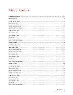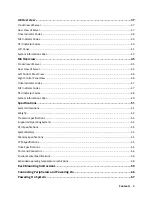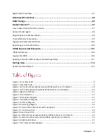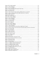
Contents 6
Table 7. PSU Indicator Diagram .................................................................................................................. 14
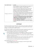
Table 8. LCD Panel Diagram ........................................................................................................................ 16
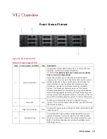
Table 9. Front View of V12 .......................................................................................................................... 18
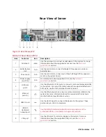
Table 10. Rear View of V12 ......................................................................................................................... 19
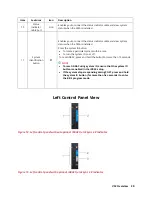
Table 11. Left Control Panel View ............................................................................................................... 21
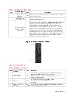
Table 12. Right Control Panel...................................................................................................................... 21
Table 13. NIC Indicator Code Diagram ........................................................................................................ 22
Table 14. PSU Indicator Code Diagram ....................................................................................................... 23
Table 15. LCD Panel Diagram ...................................................................................................................... 24
Table 16. Front View of V14 ........................................................................................................................ 27
Table 17. Rear View of V14 ......................................................................................................................... 28
Table 18. Left Control Panel View ............................................................................................................... 30
Table 19. Right Control Panel View ............................................................................................................. 31
Table 20. Drive Indicators ........................................................................................................................... 32
Table 21. NIC Indicator Diagram ................................................................................................................. 33
Table 22. PSU Indicator Diagram ................................................................................................................ 33
Table 23. LCD Panel Diagram ...................................................................................................................... 35
Table 24. Front View of A8 .......................................................................................................................... 37
Table 25. Rear View of A8 ........................................................................................................................... 38
Table 26. Drive indicators ........................................................................................................................... 38
Table 27. NIC Indicator Diagram ................................................................................................................. 39
Table 28. PSU Indicator Diagram ................................................................................................................ 40
Table 29. LCD Panel Diagram ...................................................................................................................... 42
Table 30. Setup Menu ................................................................................................................................. 42
Table 31. View Menu .................................................................................................................................. 43
Table 32. Rear View of M4 .......................................................................................................................... 45
Table 33. NIC Indicator Lights ..................................................................................................................... 48
Table 34. PSU Indicator ............................................................................................................................... 49
Table 35. System Dimensions for V8, V12, and V14 ................................................................................... 51
Table 36. Dimensions for A8 ....................................................................................................................... 52
Table 37. Dimensions for M4 ...................................................................................................................... 53
Содержание A8
Страница 1: ...rcgs20200916 2020 2020 2020 2020 2020 2020 2020 2020 2020 ...
Страница 27: ...V12 Overview 26 Figure 21 Service Information with System Touch Points ...
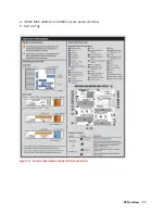
Страница 45: ...A8 Overview 44 Figure 39 System touchpoint electrical overview jumper settings and memory information ...
Страница 73: ...RAID Storage 72 Click or Choose Integrated RAID Controller 1 Figure 61 BIOS Device Settings Menu ...
Страница 75: ...RAID Storage 74 Select Virtual Disk Management Figure 63 PERC Adapter Server Profile View ...
Страница 77: ...RAID Storage 76 Under Operation choose Delete Virtual Disk Figure 65 Virtual Disk Management Select Go ...
Страница 78: ...RAID Storage 77 And Confirm that you want to Delete Figure 66 Virtual Disk Management Confirmation ...
Страница 79: ...RAID Storage 78 Once the operation has been completed click OK Figure 67 Virtual Disk Management Job Complete ...
Страница 81: ...RAID Storage 80 Select Create Virtual Disk Figure 69 Create Virtual Disk ...
Страница 82: ...RAID Storage 81 Select RAID level Figure 70 Select RAID Type ...
Страница 83: ...RAID Storage 82 Select Physical Disks Figure 71 Select Physical Disks ...
Страница 85: ...RAID Storage 84 Scroll up and Click Apply Changes Figure 73 Apply Changes ...
Страница 86: ...RAID Storage 85 Select OK Figure 74 Confirm Completion ...
Страница 88: ...RAID Storage 87 Once you have completed your settings click Create Virtual Disk Figure 76 Create Virtual Disk ...
Страница 89: ...RAID Storage 88 Confirm and Click Yes Figure 77 Confirm Operation ...
Страница 96: ...RAID Storage 95 Verify all settings and if correct click Finish Figure 84 Complete the Wizard ...

