A8 Overview 42
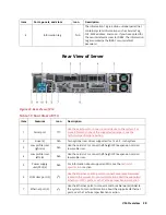
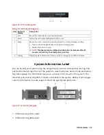
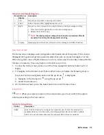
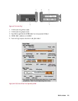
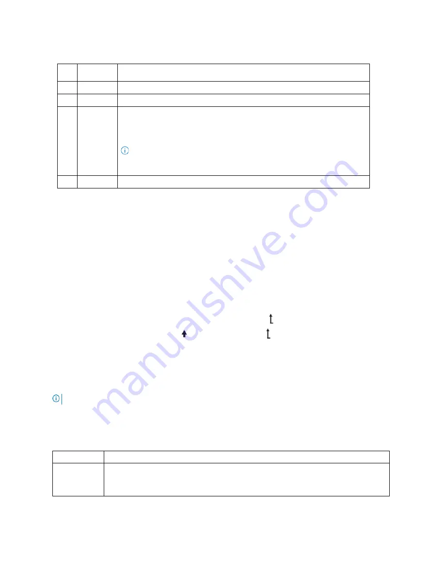
Table 29. LCD Panel Diagram
Item Button or
display
Description
1
Left
Moves the cursor back in one-step increments.
2
Select
Selects the menu item highlighted by the cursor.
3
Right
Moves the cursor forward in one-step increments. During message scrolling:
•
Press and hold the right button to increase scrolling speed.
•
Release the button to stop.
NOTE:
The display stops scrolling when the button is released. After 45
seconds of inactivity, the display starts scrolling.
4
Display
Displays system information, status, and error messages or iDRAC IP address.
View Home Screen
The Home screen displays user-configurable information about the system. This screen is
displayed during normal system operation when there are no status messages or errors.
When the system turns off and there are no errors, LCD enters the standby mode after five
minutes of inactivity. Press any button on the LCD to turn it on.
1.
To view the Home screen, press one of the three navigation buttons (Select, Left, or
Right).
2.
To navigate to the Home screen from another menu, complete the following steps: a
Press and hold the navigation button till the up arrow is displayed.
a.
Navigate to the Home icon using the up arrow .
b.
Select the Home icon.
3.
On the Home screen, press the Select button to enter the main menu
Setup Menu
NOTE:
When you select an option in the Setup menu, you must confirm the option
before proceeding to the next action.
Table 30. Setup Menu
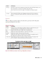
Option
Description
iDRAC
Select DHCP or Static IP to configure the network mode. If Static IP is selected, the
available fields are IP, Subnet (Sub), and Gateway (Gtw). Select Setup DNS to enable
DNS and to view domain addresses. Two separate DNS entries are available.
Содержание A8
Страница 1: ...rcgs20200916 2020 2020 2020 2020 2020 2020 2020 2020 2020 ...
Страница 27: ...V12 Overview 26 Figure 21 Service Information with System Touch Points ...
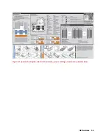
Страница 45: ...A8 Overview 44 Figure 39 System touchpoint electrical overview jumper settings and memory information ...
Страница 73: ...RAID Storage 72 Click or Choose Integrated RAID Controller 1 Figure 61 BIOS Device Settings Menu ...
Страница 75: ...RAID Storage 74 Select Virtual Disk Management Figure 63 PERC Adapter Server Profile View ...
Страница 77: ...RAID Storage 76 Under Operation choose Delete Virtual Disk Figure 65 Virtual Disk Management Select Go ...
Страница 78: ...RAID Storage 77 And Confirm that you want to Delete Figure 66 Virtual Disk Management Confirmation ...
Страница 79: ...RAID Storage 78 Once the operation has been completed click OK Figure 67 Virtual Disk Management Job Complete ...
Страница 81: ...RAID Storage 80 Select Create Virtual Disk Figure 69 Create Virtual Disk ...
Страница 82: ...RAID Storage 81 Select RAID level Figure 70 Select RAID Type ...
Страница 83: ...RAID Storage 82 Select Physical Disks Figure 71 Select Physical Disks ...
Страница 85: ...RAID Storage 84 Scroll up and Click Apply Changes Figure 73 Apply Changes ...
Страница 86: ...RAID Storage 85 Select OK Figure 74 Confirm Completion ...
Страница 88: ...RAID Storage 87 Once you have completed your settings click Create Virtual Disk Figure 76 Create Virtual Disk ...
Страница 89: ...RAID Storage 88 Confirm and Click Yes Figure 77 Confirm Operation ...
Страница 96: ...RAID Storage 95 Verify all settings and if correct click Finish Figure 84 Complete the Wizard ...

