V8 Overview 14
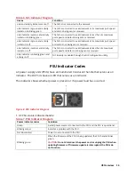
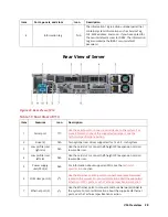
Table 6. NIC Indicator Diagram
Status
Condition
Link and activity indicators are off
The NIC is not connected to the network.
Link indicator is green and activity
indicator is blinking green
The NIC is connected to a valid network at its maximum port speed
and data is being sent or received.
Link indicator is amber and activity
indicator is blinking green
The NIC is connected to a valid network at less than its maximum
port speed and data is being sent or received.
Link indicator is green and activity
indicator is off
The NIC is connected to a valid network at its maximum port speed
and data is not being sent or received.
Link indicator is amber and activity
indicator is off
The NIC is connected to a valid network at less than its maximum
port speed and data is not being sent or received.
Link indicator is blinking green and
activity is off
NIC identity is enabled through the NIC configuration utility.
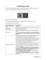
PSU Indicator Codes
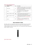
AC power supply units (PSUs) have an illuminated translucent handle that serves as an
indicator. The DC PSUs have an LED that serves as an indicator.
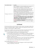
The indicator shows whether power is present or if a power fault has occurred
Figure 8. PSU Indicator Diagram
1. AC PSU status indicator/handle
Table 7. PSU Indicator Diagram
Power indicator codes
Condition
Green
A valid power source is connected to the PSU and the PSU is operational.
Blinking amber
Indicates a problem with the PSU
Not illuminated
Power is not connected to the PSU.
Blinking green
When the firmware of the PSU is being updated, the PSU handle blinks
green.
CAUTION:
Do not disconnect the power cord or unplug the PSU when
updating firmware. If firmware update is interrupted, the PSUs do
not function.
Содержание A8
Страница 1: ...rcgs20200916 2020 2020 2020 2020 2020 2020 2020 2020 2020 ...
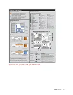
Страница 27: ...V12 Overview 26 Figure 21 Service Information with System Touch Points ...
Страница 45: ...A8 Overview 44 Figure 39 System touchpoint electrical overview jumper settings and memory information ...
Страница 73: ...RAID Storage 72 Click or Choose Integrated RAID Controller 1 Figure 61 BIOS Device Settings Menu ...
Страница 75: ...RAID Storage 74 Select Virtual Disk Management Figure 63 PERC Adapter Server Profile View ...
Страница 77: ...RAID Storage 76 Under Operation choose Delete Virtual Disk Figure 65 Virtual Disk Management Select Go ...
Страница 78: ...RAID Storage 77 And Confirm that you want to Delete Figure 66 Virtual Disk Management Confirmation ...
Страница 79: ...RAID Storage 78 Once the operation has been completed click OK Figure 67 Virtual Disk Management Job Complete ...
Страница 81: ...RAID Storage 80 Select Create Virtual Disk Figure 69 Create Virtual Disk ...
Страница 82: ...RAID Storage 81 Select RAID level Figure 70 Select RAID Type ...
Страница 83: ...RAID Storage 82 Select Physical Disks Figure 71 Select Physical Disks ...
Страница 85: ...RAID Storage 84 Scroll up and Click Apply Changes Figure 73 Apply Changes ...
Страница 86: ...RAID Storage 85 Select OK Figure 74 Confirm Completion ...
Страница 88: ...RAID Storage 87 Once you have completed your settings click Create Virtual Disk Figure 76 Create Virtual Disk ...
Страница 89: ...RAID Storage 88 Confirm and Click Yes Figure 77 Confirm Operation ...
Страница 96: ...RAID Storage 95 Verify all settings and if correct click Finish Figure 84 Complete the Wizard ...


