8
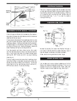
Fig.5
Especially Airtight Properties:-
If the cooker is being fitted in a property where the
design air permeability is less than 5m
3
/ (h.m
2
) (nor-
mally newer properties built from 2006), then a per-
manent ventilation must be fitted to provide 550mm
2
of ventilation for each kW of rated output. If a draught
stabiliser is also fitted then the requirement is
850mm
2
per kW of rated output.
Apply fire cement to the socket in the hob. Attach a
short length of 6” (150mm) I.D. pipe approx. 10”
(250mm) long to the outlet of the flue box by means
of fire cement. Place the flue box on the hob and the
pipe into the wall and consolidate the fluebox and pipe
into the fire cement. Apply 3 or 4 coils of 10mm (
1
/
2
’)
insulating rope to the pipe and fill the wall cavity with
fire cement. (See fig. 5).
FLUE BOX
CENTRAL HEATING AND
HOT WATER SYSTEM
THIS APPLIANCE MUST NOT BE USED WITHOUT
WATER CONNECTED.
It is recommended that a 190 litre (40 galls) indirect
hot water storage cylinder of the double feed type e.g.
(Complying with BS. 1566 Part 1:DF Type 10) should
be lagged and fixed vertically as near as possible to
the cooker.
The 28mm minimum diameter primary flow and return
pipes must not exceed 10m in length and pipes longer
than 5m must be lagged.
Ensure that the flow pipe has an open vent and rises
continuously from the boiler to the cylinder to ensure
good gravity circulation.
In combined systems, the water draw-off pipes to the
taps must be dead-leg connection from the vent/ex-
pansion pipe.
There are only two boiler tappings on this cooker and
a typical design layout is shown in Fig. 6.
An injector tee is provided which must be fitted to en-
sure adequate primary flow circulation when the water
circulator is operating, otherwise there may be a lack
of domestic hot water. The heating flow and return
pipes may be 22mm, the return pipe being connected
to the 28mm primary return by the injector tee, and
the tee outlet connected to the boiler return pipe.
All installations must be fitted with a drain tap at the
lowest point of the system.
Inhibitor
A corrosion inhibitor
MUST
be added to the heating
system to protect the heat exchanger and pipework.
Inhibitor must also be replaced if the system is
drained after installation. As a precaution, the heating
system
MUST
also be flushed out prior to the addition
of the inhibitor to ensure any flux, debris is removed.
Typical Central Heating/Hot
Water System
Fig.6
CENTRAL HEATING PUMP CONTROL
The central heating pump must be controlled by fitting
a pipe thermostat on the flow pipe as close as possi-
ble to the cooker. If it is used on its own it should be
set to approx. 55
o
C
Содержание 370 SFW
Страница 11: ...11 EXPLODED VIEW ...
Страница 13: ...13 NOTES ...
Страница 14: ...NOTES 14 ...
Страница 15: ...15 NOTES ...
Страница 29: ...13 NOTES ...
Страница 30: ...14 NOTES ...
Страница 31: ...15 NOTES ...


