

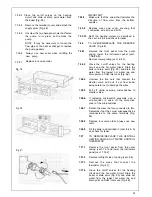


Locate the sealing washer fixing the twin flue
header as illustrated making sure that the
inner aluminium exhaust locates firmly in the
outlet spigot. Make sure that the screws are
satisfactorily located through the gasket seal.
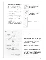
Locate the 2 x 80 mm ‘0’ rings in the twin
90” M/F bend consisting of.
90” elbow with ‘0’ ring side F
80 mm dia ‘0’ ring
f l u e h e a d e r .
Figures show the versatility of this flueing
system. Measurements and bends must be
calculated correctly so as not to oversize
maximum flue lengths.
All located ‘0’ rings must be lubricated with
a silicone grease to ensure easy, snug fit.
NOTE: Exhaust flue must slope 2” down
towards the boiler 35 mm fall per metre.
Spacing Clips
Spacing clips are available on request
should they be required.
NOTE: for eccentric vertical flue a 125 mm
(5 in) diameter flashing plate will be
required.
135” M/F bend consisting of.
135” elbow with ‘0’ ring side F
80 mm dia ‘0’ ring
Vertical eccentric flue exhaust duct
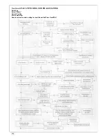
E = EXHAUST
I = INLET
T = TERMlNAL
Exhaust/suction system with concentric pipes for flat
or sloping roofs. Extensions with two separate pipes.
Maximum distance = I + E + T = 2 Metre + 2 Metre +
1 Metre = 12 Metre maximum (pipe + terminal).
Minimum distance D = T = 2 metre.
Exhaust terminal must not be cut.
NOTE: The pressure loss for each elbow fitted is:
90” slow bend less 3 metre of pipe for each one
fitted.
135” bend less 1.5 metre of pipe for each one fitted
NOTE:
If bends are used in the exhaust flue then horizontal
sections must be avoided and there must be a 2”
slope towards the boiler 35 mm fall per metre.
IMPORTANT: See Fig. 42 for terminal clearances.
51
Содержание CSI 85
Страница 26: ...27...
Страница 42: ......
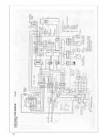
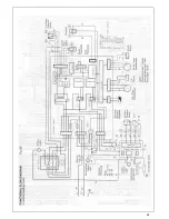
Страница 45: ...SECTION 9 ELECTRICAL SYSTEM DIAGRAM Fig 94 46...
Страница 46: ...47...
Страница 47: ......
Страница 48: ...49...
Страница 52: ......
Страница 55: ...Chartists Way Morley Leeds LS27 9ET Telephone 0113 252 7007 Tfax 0113 238 0229...


