


7.27.5 Undo the nut and withdraw the sensor
(Fig. 81) from its pocket,.
7.27.6
Replace in reverse order.
Fig. 82
Fig. 83
7.28
7.28.1
7.28.2
7.28.3
7.28.4
7.28.5
7.28.7
7.28.8
7.28.9
7.28.10
7.28.11
7.28.12
7.28.13
7.28.14
7.29
7.29.1
7.29.2
7.29.3
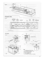
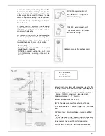
TO REMOVE/REPLACE THE CENTRAL
HEATING EXPANSION VESSEL
In the unlikely event of failure of the central
heating
expansion
vessel
i t
i s
recommended a suitable expansion vessel
be fitted external to the boiler. It should be
positioned on the return pipe and as close
to the boiler as possible (Fig. 7).
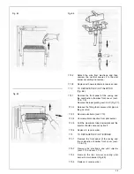
However, if it is necessary to replace the
central heating expansion vessel the boiler
must be removed from the wall as follows,
Remove the front panel from the outer
casing (sect. 7.3) and lower the instrument
panel (sect. 7.16.2 & 3) and remove the
control box cover (sect. 7.31.2/3).
Remove the lower grating (sect. 5.4.2).
Remove the two sides of the casing (sect.
5.4.5).
Close the on/off valve on the domestic cold
water, central heating and gas supply.
Drain domestic water from the lowest hot
water tap and drain point on DHW inlet
cock (Fig. 46).
Drain the boiler (Fig. 93).
Disconnect all pipework connected to
boiler.
Disconnect mains cables and any other
connections (room thermostat, programming
clock).
Remove the duct proceeding in reverse
order as described in (sect. 5.5 or 5.7).
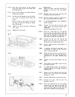
Remove the 2 lower coach bolts and
release 2 top coach bolts then remove
boiler from the wall.
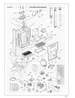
U n s c r e w t h e n u t t h a t c o n n e c t s t h e
expansion vessel and remove it (Fig. 91).
Remove the screw supporting expansion
vessel (Fig. 91).
Remove the expansion vessel.
Replace all the components in reverse
order using new seals,
Fill the system as described in the sect. 6
and check for leaks.
TO REMOVE/REPLACE THE AUTOMATIC
AIR VENT (Fig. 92)
Remove the front panel from the outer
casing and the combustion chamber front
cover (sect. 7.3 & 4).
Remove the lower grating (sect, 5.4.2).
Remove the fan assembly and the flue
hood (sect. 7.6 & 7.7).
40
Содержание CSI 85
Страница 26: ...27...
Страница 42: ......
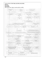
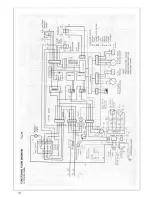
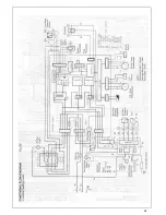
Страница 45: ...SECTION 9 ELECTRICAL SYSTEM DIAGRAM Fig 94 46...
Страница 46: ...47...
Страница 47: ......
Страница 48: ...49...
Страница 52: ......
Страница 55: ...Chartists Way Morley Leeds LS27 9ET Telephone 0113 252 7007 Tfax 0113 238 0229...


