


5.4
5.4.1
5.4.2
5.4.3
5.4.4
5.4.5
5.4.6
5.5
5.5.1
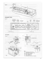
POSITIONING OF THE BOILER
Fig. 22
- Remove the 2 screws that secure the
upper part of the front panel of the
casing (Fig. 19).
- Carefully slide the front panel a few
millimetres up towards the top of the
appliance-until it is free from its slot, and
then lift off (Fig. 20).
Unscrew the 2 screws that fasten the lower
grating on the casing and remove it from the
sides of the casing (Fig. 22).
Fig. 23
Push down the 2 plastic clips that fasten the
instrument panel (Fig. 23).
Lower the instrument panel down by
rotating it on its own hinges (Fig. 25).
Unscrew the two screws fastening panels
(Fig. 21).
Remove the two sides of the casing by slightly
lifting them and carefully sliding towards the
top of the appliance, to release them from
their upper suspension hooks (Fig. 26-27).
Fig. 25
Make sure the casing and screws are put to
one side in a safe place.
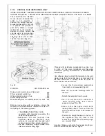
INSTALLING THE APPLIANCE FOR
REAR FLUE OUTLET
Fig. 26
Use adhesive tape to attach the template to
the wall, making sure that the centre line is
vertical.
- Mark the four boiler fastening holes on the
wall as well as the centre of the flue duct.
- Detach the template from the wall.
- Use a 10 mm. dia drill to make the 4
boiler securing holes. Insert the plastic
expansion plugs.
- Cut or cork drill a 105 mm. dia hole for
inserting the flue duct.
- Screw in the two upper coach bolts leaving
them about 10 mm. out from the wall to
enable the boiler to be located on the wall.
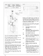
Fit the elbow header positioning it towards
the required direction (Fig. 30).
IMPORTANT:
Make sure that the elbow’s
dia. 60 mm duct is inserted into the fan, the
rubber seal and orifice (F2) have been
correctly fitted.
Fig. 21
1 8
Содержание CSI 85
Страница 26: ...27...
Страница 42: ......
Страница 45: ...SECTION 9 ELECTRICAL SYSTEM DIAGRAM Fig 94 46...
Страница 46: ...47...
Страница 47: ......
Страница 48: ...49...
Страница 52: ......
Страница 55: ...Chartists Way Morley Leeds LS27 9ET Telephone 0113 252 7007 Tfax 0113 238 0229...


