


7.2.6
7.2.6.1
7.2.7
7.2.8
7.2.9
7.3
7.3.1
7.4
7.4.1
7.4.2
7.4.3
7.4.4
7 . 6
7.6.4
Inspect the secondary condensate heat
exchanger. Deposits can be cleared by
removing and flushing out the exchanger.
Inspect the siphonic condensate trap for a
blockage. Any deposits should be flushed
out (Fig. 90).
To removecondensate trap (sect. 5.4).
Pull forward the trap (Fig. 90).
Unscrew the earth wire, and the sensor.
Replace in reverse order.
Examine the fan for any mechanical
damage, check to ensure free running of
the fan wheel. Clean the wheel if necessary
with a soft brush. Check sealing gasket and
renew if damaged (sect. 7.6).
Examine flue duct and flue hood and
e n s u r e t h a t t h e r e i s n o o b s t r u c t i o n .
Examine the gasket at the entry into the
flue duct.
It is essential that a good seal is made at
the outlet to the fan, renew this gasket if
there is any sign of damage or
deterioration.
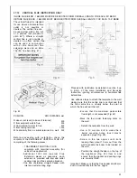
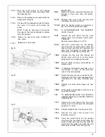
TO REMOVE/REPLACE THE FRONT
PANEL OF THE CASING (Fig. 19 & 20)
Remove the 2 screws that secure the upper
part of the front panel of the casing.
Lift the front panel few millimeters to the
top, until it is free from the slot and remove
panel.
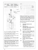
TO REMOVE/REPLACE THE COMBUS-
TION
CHAMBER COVER
Remove the front casing panel (sect. 7.3).
Unscrew all the screws that fasten the
cover to the chamber body and put them
into a container so that they don’t get lost.
Detach the cover, being careful not to
damage the seal.
Reassemble in reverse order.
Ensure good seal of cover when replacing.
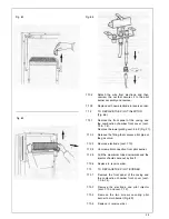
TO REMOVE/REPLACE THE FAN
nt cover
the fan motor.
from
Support the fan and remove the two fixing
screws and bracket from the front of the
flue hood.
Carefully withdraw from condensing heat
7.6.5
TO REMOVE/REPLACE CONDENSING
HEAT EXCHANGER FIG. 54-55
7.6.5.1.
7.6.5.2
Remove front casing (sect. 7.3). Remove
combustion chamber front cover as in (sect
7.4). Remove lower grating by unscrewing
the two screws (Fig. 21).
Close the ON/OFF valves for the heating.
Drain the heating system from the drain
point mounted system (Fig. 93).
7.6.5.3
7.6.5.4
Remove the fan (sect.7.6).
Disconnect 4 unions for the heating water
pipelines (Fig. 54) and remove the two
short pipes.
7.6.5.5
Remove screw holding heat exchanger to
chamber. Disconnect condensing discharge
pipe by pulling off the pushfit connector at
top rear of boiler (Fig. 54).
7.6.5.6
Pull the heat exchanger down and slightly
forward until it comes out of the connection
from chamber (Fig. 55).
7.6.5.7
Replace in reverse order. Taking care to
refit discharge pipe at rear.
IMPORTANT:
When
replacing
heat
exchanger new seals must be used.
7.7
TO REMOVE/REPLACETHE FLUE HOOD
(FIG. 60)
7.7.1
Remove front casing (sect. 7.3). Remove
combustion chamber front cover as in
(sect. 7.4).
7.7.2
Remove the fan (sect. 7.6)
7.8.11
Remove
condensing
heat exchanger
(sect. 7.6.5)
7.8
TO REMOVE THE HEAT EXCHANGER
(FIG. 62-63-64)
7.8.1
Remove front casing (sect 7.3). Remove
combustion chamber front cover as in
(sect. 7;4). Remove the lower grating
(sect.5.4.2). Lower the instrument panel
(sect. 5.4.3 & 4).
exchanger then from the appliance.
Place in a safe place until required. Reas-
semble in reverse order. Ensure wires are
connected correctly (Fig. 94).
3 2
Содержание CSI 85
Страница 26: ...27...
Страница 42: ......
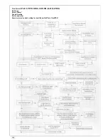
Страница 45: ...SECTION 9 ELECTRICAL SYSTEM DIAGRAM Fig 94 46...
Страница 46: ...47...
Страница 47: ......
Страница 48: ...49...
Страница 52: ......
Страница 55: ...Chartists Way Morley Leeds LS27 9ET Telephone 0113 252 7007 Tfax 0113 238 0229...


