


SIZING OF ADDITIONAL EXPANSION VESSELS: TABLE 3
Deduct from the value given in the table the 7 litre vessel supplied.
Safety
valve setting (bar)
3.0
Vessel charge
pressure (bar)
0.5
1.0
1.5
Initial System
.
pressure (bar)
0.5
1.0
1.5
2.0
1.0
1.5
2.0
1.5
2.0
Total water
content Of system
EXPANSION VESSEL VOLUME (LITRES)
Litres
2 5
2.1
3.5
6.5
13.7
2.7
4.7 10.3
3.9
6.3
5 0
4.2
7.0
12.9
27.5
5.4
9.5 20.6
7.6
16.5
7 5
6.3
10.5
19.4
41.3
6.2
14.2 30.9
11.7
24.6
19.0 41.2
100
6.3
14.0
25.9
55.1
10.9
15.6
33.1
125
10.4
17.5
32.4
66.9
13.6
23.7 51.5
19.5
41.3
150
12.5
21.0
36.6
62.6
16.3
26.5 61.6
23.4
49.6
175
14.6
24.5
45.3
96.4
19.1
33.2 72.1
27.3
57.9
200
16.7
26.0
51.6
110.2
21.6
36.0 62.4
31.2
66.2
225
16.7
31.5
56.3
124.0
24.5
42.7 92.7
35.1
74.5
250
20.6
35.0
64.7
137.7
27.2
47.5 103.0
39.0
62.7
275
22.9
36.5
71.2
151.5
30.0
52.2 113.3
42.9
91.0
300
26.0
42.0
77.7
165.3
32.7
57.0 123.6
46.6
99.3
325
27.0
45.5
64.1
179.1
35.7
61.7 133.9
50.7
107.6
350
29.1
49.0
90.6
192.6
36.1
66.5 144.2
54.6
115.6
375
31.2
52.5
97.1
206.6
40.9
71.2 154.5
56.5
124.1
400
33.3
56.0
103.6
220.4
43.6
76.0 164.6
62.4
132.4
425
35.4
59.5
110.1
239.2
46.3
80.7 175.1
66.3
140.7
450
37.5
63.0
116.5
247.9
49.0
65.5 165.4
70.2
146.9
475
39.6
66.5
123.0
261.7
51.6
90.2 195.7
74.1
157.2
500
41.6
70.0
125.9
275.5
54.5
95.0 206.0
76.0
165.5
For system volumes
other than those given
above, multiply the
0.0633
0.140
0.259
0.551
0.109
0.190 0.412
0.156
0.331
system volume by
the factor across
Note: This pressure can be increased up to 1.5 bar to suit high static head situations, see item 10, other appliance components in the
SERVICING INSTRUCTIONS.
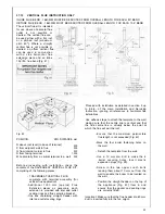
B) Where fitting a make up vessel would be
difficult re pressurisation of the system can
be done. See section on FILLING.
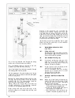
If the capacity of the central heating system
should exceed 110 litres, an additional ves-
sel should be installed on the return to the
combination boiler from the heating system
(Fig. 7). Guidance on vessel sizing is given
in (Table 3).
Reference should be made to British Gas
Publications <<Material and Installation
Specifications for Domestic Central Heating
and Hot Water>>,. Draining taps should be at
least 1/2" in BSP nominal size and be in
accordance with BS 2879.
It is most important that the correct concen-
tration of the water treatment product is
maintained in accordance with the manufac-
turers’ instructions.
If the boiler is installed in an existing system
any unsuitable additives MUST be removed
by thorough cleansing.
BS 7593:1992 details the steps necessary
to clean domestic central heating system.
Also check pipework and renew any corrod-
ed pipework or fittings. Valve glands must be
repacked or replaced wherever necessary
and any defective controls exchanged.
WATER TREATMENT
This boiler has a secondary ALUMINIUM
4.6.9
Installation to an existing central heat-
ing system
The combination boiler is designed to oper-
ate on a sealed system only. Therefore if the
existing system is of the open water type it
will have to be modified to comply with BS
5376 Part 2.
Before installing a new combination boiler to
an existing system, flush out the old system
with a recommended descaling agent.
alloy heat exchanger Ravenheat recom-
mended
only
the use of FERNOX-COPAL or
SENTINEL Xl00 water treatment products,
which must be used in accordance with the
manufacturers instructions. For further infor-
mation contact:
Fernox Manufacturing Co. Ltd.
Tel. 01799 550811
Sentinel Division Betz Dearborn Ltd.
Tel. (0151) 424 5351
14
Содержание CSI 85
Страница 26: ...27...
Страница 42: ......
Страница 45: ...SECTION 9 ELECTRICAL SYSTEM DIAGRAM Fig 94 46...
Страница 46: ...47...
Страница 47: ......
Страница 48: ...49...
Страница 52: ......
Страница 55: ...Chartists Way Morley Leeds LS27 9ET Telephone 0113 252 7007 Tfax 0113 238 0229...


