


7.82
Remove the two sides of the casing by
slightly lifting them and sliding them
towards the top of the appliance, to release
them from their upper suspension hooks.
7.84
7.8.5
Remove the fan (sect, 7.6).
Remove
condensing heat exchanger
(sect. 7.65). .
7.8.6
7.8.6
7.8.9
Remove the flue hood (sect, 7.7).
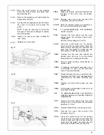
Remove the automatic air vent (Fig. 92).
Disconnect unions for two heating (right
side of boiler) water pipelines (Fig. 62).
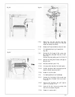
7.8.10
Unscrew the rings that fasten the heat
exchanger to the combustion chamber.
7.8.11
Remove the two side insulation panels at
top of heat exchanger (Fig. 63).
7.812
Pull the heat exchanger up until its flow
connections come out from the combustion
chamber and then remove it (Fig. 64).
7.8.13
Replace in reverse order.
Ensure correct wire position (Fig. 94).
IMPORTANT: When replacing a heat
exchanger new seals must be used.
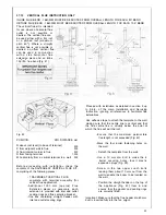
7.9
TO REMOVE/REPLACE COMBUSTION
CHAMBER INSULATION PANELS (Fig.
63).
7.9.1
Remove casing front panel (sect. 7.3).
Remove combustion chamber front cover
(sect. 7.4).
7.9.2
7.9.3
Remove fan (sect. 7.6).
Remove condensing heat exchanger (sect.
7.6.5).
7.9.4
7.9.5
Remove the flue hood (sect. 7.7).
Remove main burner (sect. 7.15).
Remove top insulation pieces at sides.
Remove 2 screws securing combustion
chamber to rear of boiler.
Lower chamber carefully remove all
insulation panels.
7.9.6
Replace in reverse order.
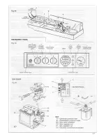
Fig. 54
Fig. 55
33
Содержание CSI 85
Страница 26: ...27...
Страница 42: ......
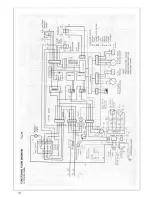
Страница 45: ...SECTION 9 ELECTRICAL SYSTEM DIAGRAM Fig 94 46...
Страница 46: ...47...
Страница 47: ......
Страница 48: ...49...
Страница 52: ......
Страница 55: ...Chartists Way Morley Leeds LS27 9ET Telephone 0113 252 7007 Tfax 0113 238 0229...


