background image

41

41

RISERVATO AL PERSONALE AUTORIZZATO ALL'INSTALLAZIONE - ONLY FOR INSTALLATION-AUTHORIZED STAFF

IST 

DEM 

ZUR 

INSTALLATION 

AUTORISIERTEN 

PERSONAL 

VORBEHALTEN 

- SEULEMENT 

POUR 

LE 

PERSONNEL 

AUTORISE 

L'INSTALLATION 

- RESERVADO 

AL 

PERSONAL 

ENCARGADO 

DE 

LA 

INSTALACION

0579-M070-0

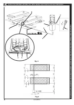
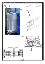
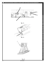
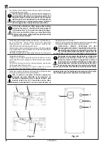
c. Verifica funzionamento micro FC1 (vedi Fig.13)

Per verificare il buon funzionamento di 

FC1 

è necessario porre

sotto la pedana 

P1 

un qualsiasi ostacolo durante la fase di discesa.

Se tutto funziona bene il sollevatore si blocca; a questo punto per
riuscire a scendere occorre risalire (è l'unica azione permessa)
fino a che non si riesce a rimuovere l'ostacolo; poi si ridiscende.

d. Comandi a uomo presente

Il sollevatore è dotato di un sistema operativo del tipo "uomo
presente", le operazioni di salita e di discesa, comandate da
pulsanti sono immediatamente interrotte al rilascio di questi ultimi.

4.16

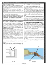
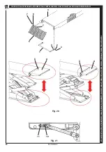
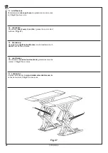
Montaggio rampine di salita

Rif. Fig. 

20

 - Montare il supporto rampa 

1

 mediante perno 

2

 e

seeger 

3

 alla pedana 

4

, poi la rampina 

5

 con perno 

6

 e seeger

7

.

Prestare attenzione a montare le rampine sul lato corretto
rispetto alle pedane. La rampina 

A

 (fig. 

20

), di lunghezza

maggiore, deve essere montata dal lato dei cilindri. La rampina

B

, di lunghezza inferiore, deve essere montata dal lato opposto

ai cilindri.Al fine di evitare lo scambio delle rampine, sulle
pedane sono presenti i perni saldati 

C

 che impediscono il

montaggio della rampina non corrispondente.

4.17

Registrazione livellamento rampine

Rif. Fig. 

21

 - Registrazione mediante vite 

10

 poi fissare con

controdado 

11

.

c. Checking that the microswitch works properly FC1 (Ref.
Fig.13)

To check that the 

FC1

 works properly, place an obstacle beneath

footboard 

P1

  as the lift is descending. If everything works

properly, the lift will stop; at this point, in order to lower the lift, you
first have to raise it (this is the only action possible) until the
obstacle can be removed; then descent can be completed.

d. "Man-present" commands

The lift is equipped with a "man-present" system of operation. The
rise and descent operations, button-controlled, come to an imme-
diate halt when the buttons are released. If this does not happen,
adjust the microswitch.

4.16 Assembling ramps

Ref. Fig. 

20

 – Fit ramp support 

1

 to platform 

4

 with shaft 

2

 and

circlip 

3

, then fit ramp

 5

 with shaft 

6

 and circlip 

7

.

Make sure the ramps are attached to the correct side of the
platforms. Ramp 

A

 (fig. 

20

), longer, must be mounted on the

cylinders side. Ramp 

B

, shorter, must be mounted opposite to

the cylinders side. To prevent confusing the ramps, the platforms
have welded pins 

C

 to avoid assembling the incorrect ramp.

4.17

Adjusting the levelling of the ramps

Ref. Fig 

21

 - Adjust using screw 

10

 then fasten with counternut

11.

c. Kontrolle der FC1 Mikroschalterfunktionstüchtigkeit (Zu
Abb.13)

Zur Kontrolle der einwandfreien Funktionstüchtigkeit des 

FC1

während der Absenkphase ein beliebiges Hindernis unter die
Fahrschiene 

P1

 stellen. Funktioniert alles einwandfrei, hält die

Bühne an; zur Wiederaufnahme der Absenkbewegung ist die
Hebebühne so lange hochzufahren (nur diese Bewegung ist
erlaubt), bis das Hindernis beseitigt werden kann; dann
herunterfahren.

d. "Totmann"-Schaltung

Die Hebebühne ist mit einem „Totmann“-Betriebssystem versehen.
Die durch Tasten gesteuerten Hub- und Absenkbewegungen
werden automatisch unterbrochen, sobald die entsprechende
Taste losgelassen wird. Sollte diese Funktion nicht erfolgen, den
Mikroschalter einstellen.

4.16 Montage der kleinen Heberampen

Bz. Abb. 

20

 – Die Rampenstütze 

1

 mit dem Zapfen 

2

 und dem

Seegerring 

3

 auf der Plattform 

4

 und dann die kleine Rampe 

5

mit dem Zapfen 

6

 und dem Seegerring 

7

 montieren.

Darauf achten, dass die kleinen seitlichen Rampen korrekt zu
den Fahrschienen montiert werden. Die längere kleine Rampe

A

 (Abb. 

20

) muss von der Seite der Zylinder her montiert werden.

Die kürzere kleine Rampe 

B

 muss von der den Zylindern

gegenüberliegenden Seite her montiert werden.Um eine
Verwechslung der kleinen Rampen zu vermeiden, wurden an
den Fahrschienen Bolzen

 C

 angeschweißt, die eine Montage

der falschen Rampe ausschließen.

4.17

Einstellung für Rampennivellierung

Zu Abb. 

21

 - Mit der Schraube 

10 

einstellen und mit der

Kontermutter 

11 

befestigen.

c. Contrôle du fonctionnement du microrupteur FC1 (Réf.
Fig.13)

Pour vérifier le bon fonctionnement de 

FC1

, il faut déposer sous le

chemin de roulement

 P1

 un obstacle quelconque pendant la phase

de descente. Si tout fonctionne comme il faut, l’élévateur se
bloque; à ce point, pour arriver à descendre, il faut faire remonter
l’élévateur (c’est l’unique manoeuvre possible) de manière à
pouvoir déplacer l’obstacle; puis, on redescend.

d. Commandes de type “homme mort”

Le pont élévateur est équipé d’un système opérationnel de type
“homme mort”. Les manoeuvres de montée et de descente
commandées par des boutons-poussoirs, sont immédiatement
interrompues au relâchement de ces derniers.  Dans le cas
contraire, il faut régler le microrupteur.

4.16 Montage des rampes de montée

Réf. Fig. 

20

– Monter le support rampe 

1

 par le biais de l’axe 

2

et de la bague

 3 

au chemin de roulement 

4

, ensuite monter la

rampe 

5

 à l’aide de l’axe 

et de la bague 

7

.

Lors du montage des rampes faire attention à les positionner sur
le côté correct par rapport aux chemins de roulement. La rampe

(fig. 

20

), de longueur majeure, doit être installée du côté des

vérins. La rampe 

B

, de longueur inférieure, doit être installée du

côté opposé aux vérins. Les goujons soudés 

C

 sur les chemins

de roulement empêchent de monter la rampe de façon erronée
et donc évitent tout échange des rampes.

4.17    Réglage du niveau des petites rampes d’accès

Réf. Fig. 

21

 - Régler en intervenant sur  la vis 

10 

et fixer  avec

le contre-écrou 

11

.

c. Comprobación funcionamiento del microinterruptor FC1
(Ref. Fig.13)

Para comprobar el correcto funcionamiento de 

FC1

 es necesario

poner debajo de la tarima 

P1

 cualquier obstáculo durante la

fase de descenso. Si todo funciona bien, el elevador se bloquea;
en este momento, para poder bajar hay que volver a subir (es
la única maniobra permitida) hasta que no se quite el obstáculo;
a continuación se vuelve a descender.

d. Sistema hombre muerto

El elevador está dotado de un sistema operativo del tipo
“hombre muerto”, mediante el cual las operaciones de subida
y bajada, con sus respectivos pulsadores de mando, se
interrumpen cuando el operador deja de maniobrar sobre
dichos pulsadores. De no ser así, regule el microinterruptor.

4.16 Montaje rampas de subida

Ref. Fig.

 20

 – Montar el soporte rampa 

1

 con el perno 

2

 y el

seeger 

3

 a plataforma 

4

, luego la rampa 

5

 con el perno 

6

 y el

seeger 

7

.

Prestar atención a montar las rampas en el lado correcto con
respecto a las plataformas. La rampa 

A

 (fig. 

20

), de mayor

longitud, debe montarse en el lado de los cilindros. La rampa

B

, de menor longitud, debe montarse en el lado opuesto al de

los cilindros. Para evitar intercambiar las rampas, en las
plataformas se encuentran los pernos soldados 

C

 que impiden

el montaje de la rampa no correspondiente.

4.17

Ajuste de la nivelación de las rampitas

Ref. Fig. 

21

 - Regule con el tornillo 

10

, luego fijar con la

contratuerca 

11

.

Содержание RAV540

Страница 1: ...en Sie sich bitte an den n chsten H ndler oder direkt an Kundendienst RAVAGLIOLI S p A Via 1 Maggio 3 40037 Pontecchio Marconi Bologna Italien Telefon 39 051 6781511 Fax 39 051 846349 e mail aftersale...

Страница 2: ...asten Attention charges suspendues Atenci n cargas suspendidas Pericolo Attenzione agli organi meccanici in movimento Danger Moving mechanical parts Gefahrt Bewegliche mechanische Organe Danger Organe...

Страница 3: ...esop rateursquiutilisentlepontdoiventpouvoirlirelanotice Aucuneresponsabilit nepeut engagerleconstructeurpourtoutd dommagementdepr judicesd coulantdunon respectdesinstructions nonc esdans cettenotice...

Страница 4: ...en und Anschluss der Hydraulikanlage in Standardposition RAV 540 27 4 5 Positionierung der Fahrschienen und Anschluss der Hydraulikanlage inStandardposition RAV540I 29 4 6 Netzanschluss 31 4 7 Versorg...

Страница 5: ...49 7 WARTUNG 50 7 1 lwechsel im Schaltschrank 50 7 2 Reinigung der Elektroventile 50 7 3 Reinigung des Stromventils 51 7 4 Schmierung 52 8 BETRIEBSST RUNGEN 55 9 EINLAGERUNG 58 10 VERSCHROTTUNG 59 SCH...

Страница 6: ...alzubeh re und ersatzteile verwenden die Hebeb hne ist durch autorisiertes Fachpersonal aufzustellen sicherstellen dassdieGummiaufnahmeneinwandfreiauf der Hebeb hne positioniert sind und das Fahrzeug...

Страница 7: ...FC1 unter der Fahrschiene P1 der die Absenkbewegung der B hne im Falle eines Hindernisses anh lt Ileststrictementinterditdesouleverdespersonnes bord des v hicules des chargements dangereux ou des expl...

Страница 8: ...e 999912520 Targhetta 380V 60Hz 3Ph 380V 60Hz 3Ph plate 999912510 Targhetta 220V 60Hz 3Ph 220V 60Hz 3Ph plate 999912390 Targhetta 230V 50Hz 3Ph 230V 50Hz 3Ph plate 3 999912380 Targhetta 400V 50Hz 3Ph...

Страница 9: ...eurencasdepannedestuyauxcaoutchouc 6 Arr t m canique de s curit sur les v rins 0 2 Informations sur les risques r siduels L l vateur objet de la pr sente notice a t fabriqu dans le respect de normes s...

Страница 10: ...10 10 0579 M070 0 1 3 1 3 1000 1700 4000 kg 1800...

Страница 11: ...enen Auflagepunktegeladenwerden F r das Anheben m ssen die mit dem Heber gelieferten Gummistopfen verwendet werden Die Stopfen sind nicht stapelbar F r das Anheben besonderer Fahrzeuge ist entsprechen...

Страница 12: ...TAMPONI H 20 mm Quantit 4 pezzi RUBBER PADS H 20 mm 4 pcs GUMITELLER H 20 mm 4 Stck TAMPONS H 20 mm 4 pi ces Rampine aggiuntive per veicoli bassi Extra ramps for low vehicles Kleine Zusatzrampen f r n...

Страница 13: ...L SPECIFICATIONS RAV540 RAV540 I Portata kg Capacity kg 4000 4000 Motore Motor 400V 50 Hz 3 Ph 2 6 kW 400V 50 Hz 3 Ph 2 6 kW Tempo salita Lifting time 46 46 Tempo discesa Descending time 27 27 Peso kg...

Страница 14: ...14 14 0579 M070 0 Fig 1 Fig 2...

Страница 15: ...se schwierige Durchg nge usw Der auszuf hrenden Arbeit angemessene Kleidung und 2 DEPLACEMENT ET PRE INSTALLATION G n ralement le pont l vateur est livr comme illustr la figure1 Lesop rationsdelevaged...

Страница 16: ...emballage leregrouper dans un endroit de ramassage inaccessible aux enfants et aux animauxetl liminerenconformit aveclesnormesenvigueur l arriv e delamarchandise v rifierl int grit de l emballage et...

Страница 17: ...weiseaufderlinkenSeite vonderZugangsseiteaus gesehen angeordnet 1100 mm von der Fahrschiene entfernt Durch die Montage eines Kits Sonderzubeh r kann der Schaltschrank in einer anderen Position als der...

Страница 18: ...Cilindro P2 Pedana P1 FootboardP1 FahrshieneP1 Chemin de roulement P1 Tarima P1 Cilindro P1 Cylinder P1 Zylinder P1 Cylindre P1 Cilindro P1 Base Basement Grundrahmen Base Base Centrale di Comando Con...

Страница 19: ...enkgeschwindigkeit Elektrohydraulische Einrichtung zum Blockieren der AbsenkbewegungbeiHindernissenunterderFahrschieneP2 ElektrischeEinrichtungzumBlockierenderAbsenkbewegung bei Hindernissen unter der...

Страница 20: ...it hydraulique et est quip d uninterrupteurg n raletdeboutons poussoirspour les manoeuvres de mont e de descente et de Stationnement optionnel En cas d urgence tourner l interrupteur g n ral sur le 0...

Страница 21: ...genausgesetzt sein dievonanderenlaufendenMaschinenverursachtwerden Am Aufstellungsort d rfen keine explosiven korrosiven und odertoxischen giftigen Materialiengelagertsein Bei der Wahl des Aufstellung...

Страница 22: ...L INSTALLAZIONE ONLY FOR INSTALLATION AUTHORIZED STAFF IST DEM ZUR INSTALLATION AUTORISIERTEN PERSONAL VORBEHALTEN SEULEMENT POUR LE PERSONNEL AUTORISE A L INSTALLATION RESERVADO AL PERSONAL ENCARGADO...

Страница 23: ...terrompono la continuit dell armatura Leareediappoggiodevonoesserepiane e livellate fra loro 0 5 cm 4 2 Preparing the installation area RAV540 The lift must be installed on flooring with sufficient re...

Страница 24: ...ALL INSTALLAZIONE ONLY FOR INSTALLATION AUTHORIZED STAFF IST DEM ZUR INSTALLATION AUTORISIERTEN PERSONAL VORBEHALTEN SEULEMENT POUR LE PERSONNEL AUTORISE A L INSTALLATION RESERVADO AL PERSONAL ENCARG...

Страница 25: ...5 lining the edges of the pit with L shaped profiled sections The characteristics of the flooring are as described in section 4 2 4 3 Vorbereitung der Aufstellungsfl che RAV540 I DieGrubegem ssAbb 5a...

Страница 26: ...FOR INSTALLATION AUTHORIZED STAFF IST DEM ZUR INSTALLATION AUTORISIERTEN PERSONAL VORBEHALTEN SEULEMENT POUR LE PERSONNEL AUTORISE A L INSTALLATION RESERVADO AL PERSONAL ENCARGADO DE LA INSTALACION 0...

Страница 27: ...tereinander richtigen Entfernung positionieren und dabei ber cksichtigen dass der Block des Ausgleichsventils gekennzeichnet mit B auf der Abb 7 am Grundrahmen der Fahrschiene P2 montiert ist Die zwei...

Страница 28: ...OR INSTALLATION AUTHORIZED STAFF IST DEM ZUR INSTALLATION AUTORISIERTEN PERSONAL VORBEHALTEN SEULEMENT POUR LE PERSONNEL AUTORISE A L INSTALLATION RESERVADO AL PERSONAL ENCARGADO DE LA INSTALACION 057...

Страница 29: ...abgebildet positionieren Gem ssAbb 8diezweimit2und3gekennzeichnetenLeitungen unter der Fahrschiene P2 herausziehen die entsprechenden Pfropfen entfernen die Leitungen durch das erdverlegte Rohr f hren...

Страница 30: ...COLLEGAMENTOMOTORE MOTORCONNECTION MOTORANSCHLUSS CONNEXIONAUMOTEUR CONEXI NDELMOTOR 400 V 50 Hz 230 V 50 Hz 26 25 400 230 0 400 230 0 26 25 10A 16A FUSIBILI FUSES SICHERUNGEN FUSIBLES FUSIBLES Versi...

Страница 31: ...orgungskabeldurchdieBohrungamKastenbodenf hrenund mitdenanderenKabelnfeststellen DieDr hteunterBer cksichtigung dernumerischen bereinstimmungandasKlemmenbrettlegen siehe Schaltplan und Abb 10 Dabei da...

Страница 32: ...NE ONLY FOR INSTALLATION AUTHORIZED STAFF IST DEM ZUR INSTALLATION AUTORISIERTEN PERSONAL VORBEHALTEN SEULEMENT POUR LE PERSONNEL AUTORISE A L INSTALLATION RESERVADO AL PERSONAL ENCARGADO DE LA INSTAL...

Страница 33: ...o y lubricado Ver Fig 11 Conectar la alimentaci n neum tica en C Conectar el tubo B a la electrov lvula EV2 Cumplir un par de carreras Accionar el pulsante de descenso y comprobar que entrelosdientesd...

Страница 34: ...Y FOR INSTALLATION AUTHORIZED STAFF IST DEM ZUR INSTALLATION AUTORISIERTEN PERSONAL VORBEHALTEN SEULEMENT POUR LE PERSONNEL AUTORISE A L INSTALLATION RESERVADO AL PERSONAL ENCARGADO DE LA INSTALACION...

Страница 35: ...a FC1 y FC2 RAV540 I Apriete el pulsador de subida y alce las plataformas de unos 50 60 cm Fig 13 Los cables del pres stato CP est n situados en la centralita hidr ulica Conecte el pres stato CP situa...

Страница 36: ...ZIONE ONLY FOR INSTALLATION AUTHORIZED STAFF IST DEM ZUR INSTALLATION AUTORISIERTEN PERSONAL VORBEHALTEN SEULEMENT POUR LE PERSONNEL AUTORISE A L INSTALLATION RESERVADO AL PERSONAL ENCARGADO DE LA INS...

Страница 37: ...v rin P1 pour purger l air il peut arriver que P2 descende puis resserrer Supprimerl alimentationpneumatiquedemani re cequel arr t m caniqueduv rinP1resteenclench surladerni redent v rin enti rementou...

Страница 38: ...rollieren Falls erforderlich die Grundrahmen zweckm ssig unterlegen Die Grundrahmen als Schablonen verwendenundmiteinem15mmBohrer 150mmtiefbohren Die L cher s ubern und die D bel mit leichten Hammersc...

Страница 39: ...2 Abb 19 ber die Schrauben der Halterung S einstellen b KontrollederDruckw chterfunktionst chtigkeit ZurKontrolledereinwandfreienDruckw chterfunktionst chtigkeit w hrend der Absenkphase ein beliebiges...

Страница 40: ...NLY FOR INSTALLATION AUTHORIZED STAFF IST DEM ZUR INSTALLATION AUTORISIERTEN PERSONAL VORBEHALTEN SEULEMENT POUR LE PERSONNEL AUTORISE A L INSTALLATION RESERVADO AL PERSONAL ENCARGADO DE LA INSTALACIO...

Страница 41: ...6 Montage der kleinen Heberampen Bz Abb 20 Die Rampenst tze 1 mit dem Zapfen 2 und dem Seegerring 3 auf der Plattform 4 und dann die kleine Rampe 5 mit dem Zapfen 6 und dem Seegerring 7 montieren Dara...

Страница 42: ...IZED STAFF IST DEM ZUR INSTALLATION AUTORISIERTEN PERSONAL VORBEHALTEN SEULEMENT POUR LE PERSONNEL AUTORISE A L INSTALLATION RESERVADO AL PERSONAL ENCARGADO DE LA INSTALACION 0579 M070 0 Fig 23 3 1 2...

Страница 43: ...RAV540 I Rif Fig 22 Posizionare il supporto 1 come a figura poi fissare con gli appositi tasselli forare con punta 10 Il supporto rampa pi grande deve essere montato dal lato dei cilindri 4 19 Fissagg...

Страница 44: ...noderaufVorrichtungen liegen die nicht in dieser Anleitung angegeben werden Die Bedienung der Hebeb hne seitens nicht entsprechend geschultemPersonal 5 2 GebrauchvonZubeh rteilen ZurVereinfachungderAr...

Страница 45: ...keine Gef hrdungen hervorgerufen werden Sobald irgendwelche Betriebsst rungen auftreten die Hebeb hne sofort anhalten und den Kundendienst des autorisierten H ndlers zu Rate ziehen Sicherstellen dass...

Страница 46: ...rkung Werden Fahrzeuge mit den Rampengummiaufnahmen1angehobensicherstellen dassdieRampenhalterung2eingesetztist sieheAbb 24 Um dies festzustellen die Fahne 3 betrachten Ist sie bodoneben kann mit den...

Страница 47: ...fases de trabajo en el autom vil pero no es obligatoria para la seguridad 5 5 Description and function of commands Ref Fig 25 Rise Main switch 1 in position 1 Press the rise button 3 until the desired...

Страница 48: ...Letztere eineUnterlegscheibelegen damitsienichteinrastenk nnen Das manuelle Absenkventil ffnen indem zuerst der Schutzst psel 1 losgeschraubt und dann die Vorrichtung 2 bet tigt wird W hrend den Notab...

Страница 49: ...gen die nicht zuvor vom Hersteller autorisiert wurden entheben diesen von der Haftungspflicht f r dadurch verursachte und entstandene Sch den DieEntfernungoderderUmbauderSicherheitseinrichtungen stell...

Страница 50: ...ReinigungderElektroventile Mit Bezug auf die Schaltpl ne der ldynamik Pneumatik und Elektroanlage wird auf der Abb 26 die Positionierung der Elektroventiledargestellt 3 Absenkelektroventil EV1 4 Pneum...

Страница 51: ...5 ist auf dem Block im Innern des Schaltschranktanks montiert Um den Zugang zu erm glichen ist der Tank zu demontieren MitBenzinundDruckluftreinigenunddieGleitf higkeit desVentill ufers berpr fen 7 3...

Страница 52: ...ths grease the cam contact surfaces 1 Fig 27 7 4 Schmierung Regelm ig ungef hr alle 6 Monate die Kontaktbereiche 1 Abb 27 der Nocken einfetten 7 4 Lubrification P riodiquement environtousles6mois grai...

Страница 53: ...re le pedane vedi paragrafo 6 1 Premere il pulsante di salita fino a mettere le pedane in arresto meccanico Eliminare l ostacolo La discesa avviene con velocit estremamente lenta a La valvola regolatr...

Страница 54: ...button until the footboards go into mechanical stop Remove obstruction To complete descent press descent button and fit pin A inside the control unit To lower the footboards see section 6 1 Press the...

Страница 55: ...r Taste Senken und Einstecken des Steckers A im Schaltschrank Fahrschienen gem ss Paragraph 6 1 herunterfahren Die Taste Heben dr cken bis die Fahrschienen mechanisch aufsetzen Das Hindernis entfernen...

Страница 56: ...la course de descente appuyer sur le bouton poussoir de descente et introduire la fiche A l int rieur du bo tier de commande Faire descendre les chemins de roulement voir paragraphe 6 1 Appuyer sur l...

Страница 57: ...scenso presione el pulsador de descenso e introduzca el enchufe A en el interior de la centralita Para que las tarimas desciendan ver p rrafo 6 1 Apriete el pulsador de subida hasta que las tarimas se...

Страница 58: ...le ou les r servoirs qui contiennent les liquides pour le fonctionnement et prot ger les parties qui risquent d tre endommag es par les d p ts de poussi res Graisser les parties qui risquent de s end...

Страница 59: ...ter la cr ation de situations de danger Estimer la classification du bien d apr s le degr d limination Eliminer au m me titre que le fer et d poser dans des centres de ramassage sp ciaux Si l quipemen...

Страница 60: ...L INSTALLAZIONE ONLYFORINSTALLATION AUTHORIZEDSTAFF IST DEM ZUR INSTALLATION AUTORISIERTEN PERSONAL VORBEHALTEN RESERVE AU PERSONNEL PREPOSE A L INSTALLATION RESERVADO AL PERSONAL ENCARGADO DE LA INST...

Страница 61: ...on fuses 10 3X38 25A 400V aM FU1 Terna fusibili protezione linea motore10 3x38 16A 500V aM versioni 230V 10 3x38 10A 500V aM versioni 400V Tern of motor line protection fuses 10 3x38 16A 500V aM versi...

Страница 62: ...NTO PNEUMATICO DIAGRAM OF PNEUMATIC SYSTEM RISERVATOALPERSONALEAUTORIZZATOALL INSTALLAZIONE ONLYFORINSTALLATION AUTHORIZEDSTAFF IST DEM ZUR INSTALLATION AUTORISIERTEN PERSONAL VORBEHALTEN RESERVE AU P...

Страница 63: ...ump E Valvola di taratura 310 bar Calibration valve 310 bar F Valvola regolazione di portata autocompensata Self balanced capacity valve G Elettrovalvola di discesa EV1 Descent solenoid valve EV1 H Fi...

Страница 64: ...AV540 A o de construcci n N merodematr cula En la primera p gina del manual 0579 M El n mero de la tabla El n mero de referencia del recambio mismo 11 2 Indice tavole ricambi La Fig 28 rappresenta l i...

Страница 65: ...NKEN TAFEL 3 FAHRSCHIENEN TAFEL 4 ZYLINDER TAFEL 5 FAHRSCHIENENAUSGLEICHSVENTIL TAFEL 6 PNEUMATIKANLAGE TAFEL 7 HYDRAULIKANLAGE TAFEL 8 LDYNAMISCHE ZENTRALE TAFEL 9 11 STEUERTAFEL TAFEL 12 SCHALTSCHRA...

Страница 66: ...0579 M070 0 30 09 14 66 N tavola Tableno Indice di modifica Changeindex Denominazione tavola Table definition Valida per i modelli Apply to models RAV540 RAV540I 1 2 SOLLEVATOREPRINCIPALE MAIN LIFT...

Страница 67: ...M070 0 30 09 14 67 N tavola Tableno Indice di modifica Changeindex Denominazione tavola Table definition Valida per i modelli Apply to models SISTEMA SGANCIO ARPIONI PAWL RELEASE SYSTEM 2 1 RAV540 RAV...

Страница 68: ...0579 M070 0 30 09 14 68 N tavola Tableno Indice di modifica Changeindex Denominazione tavola Table definition Valida per i modelli Apply to models PEDANE FOOTBOARDS 3 0 RAV540 RAV540I...

Страница 69: ...0579 M070 0 30 09 12 69 N tavola Tableno Indice di modifica Changeindex Denominazione tavola Table definition Valida per i modelli Apply to models CILINDRI CYLINDERS 4 0 RAV540 RAV540I...

Страница 70: ...30 09 12 70 N tavola Tableno Indice di modifica Changeindex Denominazione tavola Table definition Valida per i modelli Apply to models VALVOLADIALLINEAMENTO PEDANE FOOTBOARDALIGNMENT VALVE UNIT 5 0 RA...

Страница 71: ...0 0 30 09 12 71 N tavola Tableno Indice di modifica Changeindex Denominazione tavola Table definition Valida per i modelli Apply to models IMPIANTOPNEUMATICO COMPRESSED AIR SYSTEM 6 0 RAV540 RAV540I 1...

Страница 72: ...ndex Denominazione tavola Table definition Valida per i modelli Apply to models IMPIANTOIDRAULICO HYDRAULICSYSTEM RAV540 RAV540I 7 4 11 12 TAVOLA2 TABLE 2 7 8 4 13 12 3 3 TAVOLA5 TABLE 5 TAVOLA2 TABLE...

Страница 73: ...avola Tableno Indice di modifica Changeindex Denominazione tavola Table definition Valida per i modelli Apply to models 8A 0 CENTRALINAOLEODINAMICA MOTORE TRIFASE 50 60 Hz HYDRAULICCONTROLBOX 50 60Hz3...

Страница 74: ...vola Tableno Indice di modifica Changeindex Denominazione tavola Table definition Valida per i modelli Apply to models RAV540 RAV540I 8B 0 CENTRALINAOLEODINAMICA MOTORE MONOFASE 60 Hz HYDRAULICCONTROL...

Страница 75: ...vola Tableno Indice di modifica Changeindex Denominazione tavola Table definition Valida per i modelli Apply to models RAV540 RAV540I 8C 0 CENTRALINAOLEODINAMICA MOTORE MONOFASE 50 Hz HYDRAULICCONTROL...

Страница 76: ...09 12 76 N tavola Tableno Indice di modifica Changeindex Denominazione tavola Table definition Valida per i modelli Apply to models PANNELLODICOMANDO TRIFASE50 60Hz CONTROLPANEL 50 60Hz3 PHASE 9A 1 RA...

Страница 77: ...tavola Tableno Indice di modifica Changeindex Denominazione tavola Table definition Valida per i modelli Apply to models PANNELLODICOMANDO MOTOREMONOFASE50 60Hz CONTROLPANEL SINGLE PHASE MOTOR 50 60...

Страница 78: ...Indice di modifica Changeindex Denominazione tavola Table definition Valida per i modelli Apply to models RAV540 RAV540I PANNELLODICOMANDO TRIFASE 50 60Hz conpulsantedistazionamento CONTROLPANEL 50 6...

Страница 79: ...0579 M070 0 30 09 12 79 N tavola Tableno Indice di modifica Changeindex Denominazione tavola Table definition Valida per i modelli Apply to models MOBILECENTRALINA CONTROLUNIT 12 0 RAV540 RAV540I...

Страница 80: ...ns please have routine inspections performed by specialized personnel WICHTIG Wir bitten Sie zu ber cksichtigen dass regelm ige Kontrollbesuche seitens des Installateurs besonders wichtig sind und bit...

Страница 81: ...ollofunzionamentopressostato o Controllofunzionamentocicalino o Controllo tempi di salita e discesa a pieno carico DATA FIRMA INSTALLATORE FIRMA UTILIZZATORE INITIAL INSTALLATION INSPECTIONS LIFT TYPE...

Страница 82: ...r le du fonctionnement du pressostat o Contr le du fonctionnement de l avvertiseur sonore o Contr le de la dur e des courses de mont e et de descente pleine charge DATE SIGNATURE DE L INSTALLATEUR SIG...

Страница 83: ...seponiendoeventualmenteespesores o Apretamiento tacos sujeci n bases al suelo o Apretamiento tubos hidr ulicos de centralita a bases o Control del nivel del aceite centralita o Control uni n red y con...

Страница 84: ...desFahrschienen AusgleichsventilsunddesFahrschienenausgleichs o Kontrolle des Einrastens der Sperrklinken auf den Zylindern o KontrollederDruckw chter Funktionst chtigkeit o KontrollederSummer Funktio...

Страница 85: ...desFahrschienen AusgleichsventilsunddesFahrschienenausgleichs o Kontrolle des Einrastens der Sperrklinken auf den Zylindern o KontrollederDruckw chter Funktionst chtigkeit o KontrollederSummer Funktio...

Страница 86: ...desFahrschienen AusgleichsventilsunddesFahrschienenausgleichs o Kontrolle des Einrastens der Sperrklinken auf den Zylindern o KontrollederDruckw chter Funktionst chtigkeit o KontrollederSummer Funktio...

Страница 87: ...desFahrschienen AusgleichsventilsunddesFahrschienenausgleichs o Kontrolle des Einrastens der Sperrklinken auf den Zylindern o KontrollederDruckw chter Funktionst chtigkeit o KontrollederSummer Funktio...

Страница 88: ...desFahrschienen AusgleichsventilsunddesFahrschienenausgleichs o Kontrolle des Einrastens der Sperrklinken auf den Zylindern o KontrollederDruckw chter Funktionst chtigkeit o KontrollederSummer Funktio...

Страница 89: ...89 0579 M070 0 VERIFICA OCCASIONALE DATA FIRMA DELL INSTALLATORE RANDOM INSPECTIONS DATE INSTALLER SIGNATURE...

Страница 90: ...90 0579 M070 0 GELEGENTLICHE KONTROLLE DATUM UNTERSCHRIFT DES MONTEURS CONTROL OCCASIONNEL DATE SIGNATURE DE L INSTALLATEUR...

Страница 91: ...91 0579 M070 0 CONTROL OCASIONAL FECHA FIRMA DEL INSTALADOR...

Страница 92: ...r teilweise den Vorfall unverz glichdemHerstellermelden ATTENTION Il est strictement interdit de falsifier de graver de modifier de quelque fa on que ce soit ou d enlever la plaque d identification de...

Страница 93: ...Pagina bianca per esigenze di impaginazione This page intentionally blank Freie Seite f r Layout Page blanche pour exigences de mise en page P gina en blanco por exigencias de compaginaci n 0579 M070...

Страница 94: ...opea La macchina risponde alle seguenti Direttive applicabili 2006 42 CE Direttiva Macchine 2014 30 EU Direttiva Compatibilit Elettromagnetica 2014 35 EU Direttiva Bassa Tensione 5 all occorrenza nome...

Страница 95: ...with the following applicable Directives 2006 42 EC Machinery Directive 2014 30 EU Electromagnetic Compatibility Directive 2014 35 EU Low Voltage Directive 5 where appropriate the name address and ide...

Страница 96: ...hen Union ver ffentlichten Texte entsprechen Die Maschine entspricht folgenden geltenden Richtlinien 2006 42 EG Maschinenrichtlinie 2014 30 EU Richtlinie ber die elektromagnetische Vertr glichkeit 201...

Страница 97: ...de l Union europ enne La machine est conforme aux directives applicables suivantes 2006 42 CE Directive Machines 2014 30 EU Directive Compatibilit lectromagn tique 2014 35 EU Directive Basse Tension...

Страница 98: ...con las siguientes Directivas aplicables 2006 42 CE Directiva de M quinas 2014 30 UE Directiva de Compatibilidad Electromagn tica 2014 35 UE Directiva de Baja Tensi n 5 en su caso el nombre la direcc...

Отзывы: