background image

M3SR Series 4100

Control and Monitoring of Radio and Control Unit

3.34

Operating Manual 6175.4760.02 – 01

3.3.1.2

Disconnecting from Radio

Press the softkey 'Disconnect from Radio' if you no longer wish to control or monitor the radio 
you are connected to. If you want to control or monitor another radio, also press the softkey 
'Disconnect from Radio'. To connect to another radio see ”Connecting to Radio” on p. 3.30.

After pressing the softkey 'Disconnect from Radio' you will see the Home menu as shown in 
Figure 3.14.

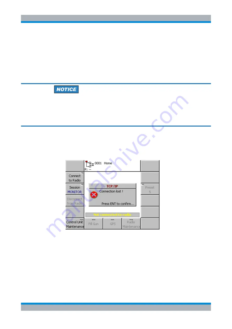
A control unit may be disconnected from a radio automatically. This may be due to 
switching off the radio or due to a broken LAN. In any case a message box 'TCP/IP 
Connection Lost' pops up and the GUI automatically navigates to the Home menu (see 
Figure 3.18
).

Figure 3.18 Connection Lost

In case of a broken (or too slow) LAN connection, the GUI temporarily changes to the 'Check 
Connection' state. In this state the GUI tries to reconnect to the radio for a short time. The 
status 'Check Connection' can be seen in the menu header (R: ??). If the reconnection was 
successful, the connection state changes to Connected. If reconnecting fails, the connection 
state changes to Disconnected (R: --).

ICN-4D-G-231000-R-D0894-00034-A-01-1

Содержание M3SR 4100 Series

Страница 1: ...Operating Manual Radiocommunications Systems 6175 4760 02 01 R S M3SR Series 4100 Software Defined Radios Operating Manual...

Страница 2: ...de Schwarz GmbH Co KG Muehldorfstr 15 81671 Munich Germany Phone 49 89 4129 0 Fax 49 89 4129 12164 E mail info rohde schwarz com Internet http www rohde schwarz com Printed in Germany Subject to chang...

Страница 3: ...automatic level control ALE automatic link establishment ALE 2G automatic link establishment 2nd generation ALE 2G LP automatic link establishment 2nd generation with linking protection ALE 3G automat...

Страница 4: ...IR Comit Cosultatif International de Radiocommunication CLARIF clarifier frequency CLR clear Comp component COMSEC communication security ConMode connection mode CONFIG configuration CR connect reques...

Страница 5: ...EC forward error correction FED STD Federal Standard FF fixed frequency FHS free hopset search FLM fast link mode FLSU fast link setup FM frequency modulation FREQ frequency FSK frequency shift keying...

Страница 6: ...nternational Electrotechnical Commission IF intermediate frequency IGMP internet group management protocol IHBT inhibit INDV individual INT internal INTL interleaver length INTLV interleaver length IN...

Страница 7: ...MBE LPC multiband excitation linear predictive coding MC multicast MD mode MDL middle MELP mixed excitation linear prediction MGC manual gain control MIL STD military standard MMBE modified multi band...

Страница 8: ...rd authentication protocol PAvg average power factor PBIT power on built in test PBT passband tuning frequency PC personal computer PDU protocol data unit PEP peak envelope power PH phase PMU power ma...

Страница 9: ...commands RGA radio global address RIT receiver incremental tuning RNMS3000 radio network management system ROB robust RPT report RQ request RSSI received signal strength indication RTC real time clock...

Страница 10: ...control Protocol Thres threshold TLC transmitter level control TOS type of service TRANSEC transmission security TRU time reference unit TTL time to live TTY teletypewriter Tx transmit transmitter U U...

Страница 11: ...Operating Manual 6175 4760 02 01 ix M3SR Series 4100 Abbreviations W WARC World Administrative Radio Conference WF waveform Wild wildcard X xDL ARQ protocols x H or L...

Страница 12: ...whether all mentioned requirements are met or all measures are tak en to establish the required condition Open Access is to be gained to the unit module by observing the given instructions and safety...

Страница 13: ...radio on separate order only The Getting Started manual provides the information needed to set up and start working with the radio The Getting Started manual includes general information e g Basic Saf...

Страница 14: ...lable in PDF format on the CD ROM deliv ered with the radio The printed manual can be ordered from Rohde Schwarz GmbH Co KG Service Manual Intermediate Level on separate order only delivered with the...

Страница 15: ...M3SR Series 4100 Documentation Overview xiv Operating Manual 6175 4760 02 01...

Страница 16: ...Communication 1 15 1 9 Radio Control 1 16 1 9 1 Radio with Several Control Units 1 18 1 9 2 Several Radios and Control Units in a Network 1 20 2 Getting Started 2 1 2 1 Unpacking Checking Packing Tran...

Страница 17: ...n 3 11 3 2 2 3 Menu Page Design 3 11 3 2 2 4 Icons and Symbols 3 13 3 2 2 5 Softkeys 3 16 3 2 2 6 Menu Organization 3 20 3 2 2 7 Menu Tree 3 25 3 2 2 8 Navigation within the Menu Tree 3 27 3 3 Control...

Страница 18: ...5 4 Control Unit MTC 4 4 4004 3 120 3 6 User Level 3 122 3 7 Fixed Frequency 3 126 3 7 1 Fixed Frequency Menu Tree 3 126 3 7 1 1 Fixed Frequency Home Menu 3 127 3 7 2 Fixed Frequency Operational Menu...

Страница 19: ...3 1 Starting ATU Learning 3 171 3 7 3 2 Switching ATU Silent Tuning On or Off 3 172 3 7 3 3 Bypassing the ATU 3 173 3 7 3 4 Changing the A1A Holdtime 3 174 3 7 3 5 Switching Environment Shore or Ship...

Страница 20: ...t 2nd Generation ALE 2G 4 3 4 3 1 Basics of ALE 2G 4 3 4 3 1 1 Selective Call and Handshake 4 3 4 3 1 2 Link Quality Analysis and Automatic Link Establishment 4 3 4 3 1 3 Message Transmission 4 3 4 3...

Страница 21: ...BT Timeout 4 46 4 3 6 11 Changing the Link Timeout 4 47 4 3 6 12 Switching the Sounding On or Off 4 48 4 3 6 13 Changing the Sounding Interval 4 49 4 3 6 14 Changing the Date and Time 4 50 4 3 6 15 Sw...

Страница 22: ...3 Changing the Link Timeout for Analog Voice FF Links 4 92 4 4 5 4 Changing the Timeout for Data Links 4 93 4 4 5 5 Deleting the LQA Table 4 94 4 4 5 6 Switching the Priority Based Session Management...

Страница 23: ...Changing the Modem Doppler Tracking Time 4 135 4 5 4 3 Enabling the Modem Synchronization on Data Function 4 136 4 5 4 4 Changing the Maximal Message Block Length 4 137 4 5 4 5 Changing the Modem Tx...

Страница 24: ...9 Initiating Time Acquisition 4 174 4 8 3 10 Switching the VOX Signal Source 4 175 4 8 3 11 Starting ATU Learning for SECOM H Hopset 4 176 4 8 3 12 Selecting a Hopset 4 178 4 8 3 13 Selecting a Keyset...

Страница 25: ...iating a GPS Information Request Pull Scheduled as Controller Feature 5 27 5 2 2 9 Initiating an Auto Push List Request Transmission as Controller Feature 5 28 5 2 2 10 List of Received GPS Position I...

Страница 26: ...of Voice over IP VoIP 5 101 5 5 1 1 Configuration Scenarios 5 102 5 5 1 2 General Constraints 5 109 5 5 1 3 Call Session 5 109 5 5 1 4 Phone Service 5 110 5 5 1 5 Scenario Call Session between a Radio...

Страница 27: ...Maintenance 7 2 7 1 1 Synthesizer Calibration 7 4 7 1 1 1 Required Test Equipment 7 4 7 1 1 2 Calibration Procedure 7 4 7 1 1 3 Possible Errors during Calibration 7 10 7 2 Care Cleaning 7 11 7 2 1 Ca...

Страница 28: ...190 2 17 Figure 2 8 System Cabling for Transceiver 2 20 Figure 2 9 Switching the Radio On 2 23 Figure 2 10 Switching the Radio with Built In Control Unit On 2 24 Figure 2 11 Example for the Automatic...

Страница 29: ...2 Figure 3 26 Navigation Softkeys to Communication Mode Submenus 3 43 Figure 3 27 Preset Page Selection Example 3 45 Figure 3 28 Fill Gun Navigation Softkey Example 3 46 Figure 3 29 Maintenance Naviga...

Страница 30: ...117 Figure 3 66 Menu 4004 CU MTC 4 4 3 120 Figure 3 67 Menu 4001 CU MTC 1 4 3 123 Figure 3 68 User Level Editor 3 123 Figure 3 69 Unlock 3 125 Figure 3 70 Menu Tree Fixed Frequency 3 126 Figure 3 71 H...

Страница 31: ...18 Menu 1211 ALE OP 1 2 ALE 3G 4 76 Figure 4 19 Menu 1212 ALE OP 2 2 ALE 3G 4 77 Figure 4 20 Menu 1221 ALE CFG 1 4 ALE 3G 4 84 Figure 4 21 Menu 1222 ALE CFG 2 4 ALE 3G 4 86 Figure 4 22 Menu 1223 ALE...

Страница 32: ...15 Local Voice Selection on MMI 5 59 Figure 5 16 Voice Forwarding Selection on MMI 5 61 Figure 5 17 Relay Scenario 5 63 Figure 5 18 Relay IP Broadcast Selection on MMI 5 65 Figure 5 19 Local Voice Sel...

Страница 33: ...e g XK 4115 Date of Battery Installation 7 2 Figure 7 2 Fixing the Cover to the Front Panel 7 3 Figure 7 3 Radio Maintenance Menu Calibration not Allowed 7 5 Figure 7 4 Radio Maintenance Menu Calibra...

Страница 34: ...n Buttons 3 28 Table 3 14 Session Types 3 39 Table 3 15 Softkeys in Menu Radio MTC 1 7 3001 3 51 Table 3 16 Softkeys in Menu Radio Error List 3011 3 56 Table 3 17 Softkeys in Menu Radio Error Details...

Страница 35: ...5 Waveform Message 4 107 Table 4 6 Data Rates and Interleaver Setting Dependencies on the Waveform 4 129 Table 4 7 Dependency of Tolerable Deviation on Selected Search Pattern 4 171 Table 4 8 Dependen...

Страница 36: ...Configuration Menus 4 62 ALE 2G ALE 3G HF Modem Operational and Configuration Menus 4 65 ALE 3G ALM Enable 4 112 ALE 3G Configuration Menus 4 84 ALE 3G Home Menus 4 74 ALE 3G Linking Protection 4 111...

Страница 37: ...ock Length 4 137 Changing the MGC Level 3 145 Changing the Modem DeAcquire Limit 4 134 Changing the Modem Doppler Tracking Time 4 135 Changing the Modem TX Level Control Blocks 4 138 Changing the Modu...

Страница 38: ...Display of the xDL Port Setting 4 87 Displaying Received RX Messages 4 31 Download from Fillgun into Radio 3 191 Download from PC into Radio via Serial Cable 3 186 Download in Progress Example 3 189...

Страница 39: ...3 217 Home Menu ALE 2G Listening Rx Mode 4 12 ALE 2G Listening Tx Mode 4 13 ALE 3G Listing Rx Mode 4 74 ALE 3G Listing Tx Mode 4 74 FF SCAN 3 201 Fixed Frequency e g F3E Operation Mode Rx Mode 3 127 H...

Страница 40: ...66 Local Voice Selection on MMI 5 66 Lock Channel 3 210 Lock Frequency or Channel 3 210 Locked Softkey 3 20 LOW RXREF LEVEL 7 10 LQA Calls 4 5 LQA Exchange 4 102 LQA Mode 4 103 LQA Report 4 40 LQA Re...

Страница 41: ...List 3011 3 55 Menu Radio Error List Example 6 6 Menu Radio Inventory 3021 3 59 Menu Radio Inventory Indicating a Defective Module Example 6 6 Menu Radio MTC 1 6 Indicating an Error Example 6 5 Menu R...

Страница 42: ...Messages 4 38 Position Accuracy 5 22 Possible Errors during Calibration 7 10 Power Level 3 158 4 32 4 173 Power Supply 1 8 Power On Built In Test PBIT 6 5 PPP IP Interface Address 5 73 Preamplifier 3...

Страница 43: ...ng the Active COMSEC Key for SDV Communication 4 153 Selecting the Address for Broadcast Call 4 82 Selecting the Address for Individual Call 4 17 Selecting the Address for Multicast Call 4 78 Selectin...

Страница 44: ...oftkey Data Link Timeout 4 93 Softkey Data Mode 3 83 Softkey Data Params 3 83 Softkey Datarate 4 187 Softkey Date Time 3 77 4 50 4 192 Softkey DCD Mode 3 84 Softkey Deacquire 4 134 Softkey Default LM...

Страница 45: ...Softkey Notch 3 156 Softkey OD 4 106 Softkey Op Mode 4 142 Softkey OpMode 5 79 Softkey OSC 3 51 Softkey Other Pos List OPL 5 30 Softkey Passive Time ACQ 4 51 4 104 Softkey PBT 3 157 Softkey Play LDV M...

Страница 46: ...2 3 75 Softkeys in Menu Radio MTC 3 7 3003 3 82 Softkeys in Menu Radio MTC 6 7 3 70 3 95 3 96 Softkeys in Menu Split Site 2 2 3 72 Softkeys in Menu VoIP 1 2 3 79 Softkeys in Menu VoIP 2 2 3 81 Softkey...

Страница 47: ...y Definition 4 6 Timeout for Data Links 4 93 Toggle softkey 3 17 Tones 3 8 TRANSEC 4 158 Transmitter Receiver Signal Polarity 3 166 Transport 2 2 Transport Layer 5 36 Troubleshooting 6 3 TTY RUN STOP...

Страница 48: ...M3SR Series 4100 Index 34 Operating Manual 6175 4760 02 01 ZF4401 mod 02 2 10...

Страница 49: ...ferences are pointed out where necessary Table 1 1 Applicable Software and Software Options Option Keys DS 4100A DS 4100D R S MR4100E HF Receiver Basic x x R S MR4100G HF Receiver Exciter Basic x x R...

Страница 50: ...ion ETSI EN 300 373 1 7 6 Corrosion Test The device must be operated in a room where it is protected against the effects of cor rosive environment 1 1 General Features Figure 1 1 R S M3SR Series 4100...

Страница 51: ...ping and provide interoperability with the R S M3TR Family R S M3SR Series 4100 offers solutions to all aspects of HF radiocommunications as well as a uniform interlogistics concept The transceiver fa...

Страница 52: ...itable even for difficult environmental conditions Excellent reliability Hardware complies with relevant MIL standards dealing with environmental conditions Powerful built in test BIT with clear text...

Страница 53: ...Supply Receiver Power Supply Receiver Exciter Power Amplifier Transceiver PMU Unit Power Management Unit Frontend Synthesizer Radio Controller Interface Module Antenna Interface Additional internal h...

Страница 54: ...Series 4100 User Information 1 6 Operating Manual 6175 4760 02 01 Figure 1 2 R S M3SR Series 4100 Radio e g Transceiver Top View without Cover Example 1 2 3 4 5 6 7 8 ICN 4D F 231000 R D0894 00005 A...

Страница 55: ...rating Manual 6175 4760 02 01 1 7 M3SR Series 4100 User Information 1 Interface Module 2 Power Amplifier 3 Front Panel 4 R S GB4000C option 5 R S FK4120 option 6 Synthesizer 7 Frontend 8 Radio Control...

Страница 56: ...on of the frontend In transmit operation the signal generation of the modulated carrier at 48 kHz is achieved by a direct digital synthesizer DDS with a digital quadrature modulator Afterwards the IF...

Страница 57: ...Operating Manual 6175 4760 02 01 1 9 M3SR Series 4100 User Information 1 6 General Data For more information refer to sect 9 Drawings...

Страница 58: ...Receiver No power supply is required The internal Power Supply R S IN4400A needs an input voltage of 100 V AC to 240 V AC 50 Hz to 60 Hz The radio may also be powered by an external battery 19V DC to...

Страница 59: ...upply is available in several models which are designed for different input voltages see table overleaf All models support emergency operation 21 V DC to 29 5 V DC I 35 A The DC cable is not supplied...

Страница 60: ...0705 02 02 1 3PH n 230 V AC 1PH 10 15 47 to 63 208 V AC 10 15 47 to 63 230 V AC Y 10 15 47 to 63 R S IN4190 6120 2708 02 02 1 3PH n 230 V AC 1PH 10 15 47 to 63 208 V AC 10 15 47 to 63 230 V AC Y 10 15...

Страница 61: ...t unit see Figure 1 4 available for the purpose The connecting cable between radio and R S IN4000A is available on demand The radio may also be powered by an external battery 19 V DC to 31 V DC An aut...

Страница 62: ...band and carrier AM A3E Single sideband full carrier AME H3E Single sideband reduced carrier A3A R3E Single sideband upper sideband suppressed carrier USB J3E Single sideband lower sideband suppresse...

Страница 63: ...2400 bit s and 600 bit s The MMBE Mixed Multiband Excitation vocoder with a code rate of 2400 bit s and 1200 bit s 1 8 2 Data Communication The software loadable modems provide for data communication...

Страница 64: ...sect 3 Operation The radio as stand alone tabletop unit with built in control unit is shown in Figure 1 5 Figure 1 5 Radio with Built In Control Unit 1 Built In Control Unit 2 Radio Front Panel The ra...

Страница 65: ...SR Series 4100 Radio Control Figure 1 6 Radio with Additional Remote Control Unit 1 Remote Control Unit 2 Network LAN the Radio and Control Unit are connected to 3 Radio with Built In Control Unit 1 2...

Страница 66: ...to the fact that the radio with all parts necessary for transmitting receiving and data processing can operate completely independent of the control unit In the same way the control unit is independe...

Страница 67: ...Radio Control Figure 1 7 Radio with Built In Control Unit and with two Remote Control Units 1 Remote Control Unit 2 Network LAN the Radio and Control Units are connected to 3 Radio with Built In Cont...

Страница 68: ...radios and control units may be connected to a local area network LAN see Figure 1 8 Each radio and each control unit is identified by a unique IP address The control units can reach the radios in th...

Страница 69: ...al Radios and Remote Control Units in a Network Example 1 Radio with Built In Control Unit 2 Radio without Built In Control Unit 3 Remote Control Unit 4 Hub Network Component 5 Router Network Componen...

Страница 70: ...M3SR Series 4100 Radio Control 1 22 Operating Manual 6175 4760 02 01...

Страница 71: ...Schwarz for service You can find the current address of your representa tive on our homepage www rohde schwarz com Navigate to Service Support Service Locations 2 1 2 Packing Prior to any transport c...

Страница 72: ...emperature see the data sheet Store the unit in a dry dust free place Otherwise pack the unit e g seal it in antistatic foil Unless otherwise specified we recommend to put the unit into operation once...

Страница 73: ...he innermost slide to the right hand side panel of the radio with four Phillips screws and the associated washers 4 Take the left hand telescopic slide and extend it as far as possible 5 Press the aut...

Страница 74: ...Installation and Removal 2 4 Operating Manual 6175 4760 02 01 Figure 2 1 Installation into a 19 Rack Example 12 4 26 4 42 9 35 9 7 4 29 5 29 1 92 1 92 1 92 1 1 2 3 16 11 2 4 5 6 ICN 4D G 231000 R D08...

Страница 75: ...Telescopic slide Ident no 0657 5807 00 6105 9263 00 5 Extension of the telescopic slide 377 7 mm 530 1 mm 6 Side length 457 2 mm 508 mm The telescopic slides are available on demand Ident no 0657 5807...

Страница 76: ...rding to DIN EN IEC 61010 UL 3111 CSA C22 2 No 1010 1 or DIN EN IEC 60950 UL 1950 CSA C22 2 No 950 have to be fulfilled The R S M3SR Series 4100 radio includes a single mode transceiver which is a cla...

Страница 77: ...2113 6 LAN Connector X20 7 REMOTE Connector X24 8 RCB SER Connector X21 control 9 DATA RS232 Connector X23 10 AUDIO PTT Connector X26 11 EXT SYNC Connector X10 12 not used in this application 13 Conne...

Страница 78: ...uble insulation according to DIN EN IEC 61010 UL 3111 CSA C22 2 No 1010 1 or DIN EN IEC 60950 UL 1950 CSA C22 2 No 950 have to be fulfilled The R S M3SR Series 4100 radio includes a single mode transc...

Страница 79: ...ternal power amplifier e g R S VK4150 or R S VK4190 8 DATA RS232 Connector X23 9 AUDIO PTT Connector X26 10 EXT SYNC Connector X10 11 Connector X31 DC IN to external power amplifier e g R S VK4150 or...

Страница 80: ...mission danger ous high voltages and electromagnetic fields are produced Respect the instructions of DIN VDE 0842 2 and the ICNIRP international commission on non ionizing radia tion protection guidel...

Страница 81: ...ector X23 9 AUDIO PTT Connector X26 10 EXT SYNC Connector X10 11 Connector X31 DC IN 12 Connector X32 BATTERY to external battery 13 not used in this application The cable between connector X31 DC IN...

Страница 82: ...ovide appropriate lightning protection and grounding The R S M3SR Series 4100 radio includes a single mode transceiver which is a class 1 laser product It complies with EN 60825 1 and FDA 21 CFR 1040...

Страница 83: ...SR Series 4100 Rear Cabling for Power Management Unit Necessary cabling at the rear side Figure 2 5 Rear Connectors of Power Management Unit ICN 4D C 231000 R D0894 00008 A 01 1 1 2 3 9 10 11 12 14 16...

Страница 84: ...Connector X23 13 DELAY A Connector X637 14 AUDIO PTT Connector X26 15 HF Connector X636 FROM PMU to external PMU 16 EXT SYNC Connector X10 17 RCB SER Connector X436 FROM PMU to external PMU 18 Connect...

Страница 85: ...2 15 M3SR Series 4100 Front Cabling 2 4 Front Cabling Necessary cabling at the front side Figure 2 6 Front Cabling 1 Headset Connector for e g R S GA3002 2 Fillgun Connector for e g R S GP3000 ICN 4D...

Страница 86: ...while transmission is in progress During transmission danger ous high voltages and electromagnetic fields are produced Respect the instructions of DIN VDE 0842 2 and the ICNIRP international commissio...

Страница 87: ...Operating Manual 6175 4760 02 01 2 17 M3SR Series 4100 System Cabling Figure 2 7 Cabling between R S GX4100A D R S VK4190 and R S IN4190 ICN 4D C 231000 R D0894 00014 A 02 1 1 2 3 4 5 6 7 8 9 10...

Страница 88: ...X23 power supply X33 R S GK4106 6120 3656 03 03 30 m 5 DC Cable power amplifier X21 power supply X34 R S GK4107 6120 3704 03 03 3 m 6 Ground Connection M6 7 Antenna Tuning Unit Connection Control R S...

Страница 89: ...e transmission is in progress During transmission danger ous high voltages and electromagnetic fields are produced Respect the instructions of DIN VDE 0842 2 and the ICNIRP international commission on...

Страница 90: ...Connection 2 Ground Connection 3 Ground Connection M6 4 DC cable R S IN4000A Power Supply R S XK4115 for instance R S GK4103 6120 5807 xx xx 05 0 5 m 10 1 0 m 25 2 5 m 5 Antenna Tuning Unit Connectio...

Страница 91: ...the antenna while transmission is in progress During transmission danger ous high voltages and electromagnetic fields are produced Respect the instructions of DIN VDE 0842 2 and the ICNIRP internatio...

Страница 92: ...erface de scription sect 9 Drawings For basic information see sect 2 5 System Cabling The connections receiver exciter X31 power amplifier X24 power amplifier X23 power supply X34 ground connection ma...

Страница 93: ...at the following minimum requirements are met Power supply is switched on see the power supply documentation Check relevant rear and front cabling See sect 2 3 Rear Cabling sect 2 4 Front Cabling sect...

Страница 94: ...2 10 Switching the Radio with Built In Control Unit On 1 Radio Button ON OFF 2 Radio LED AC DC 3 Radio LED BATT Battery 4 Radio LED GO 5 Control Unit Button ON OFF 6 Control Unit LED ON 7 Control Uni...

Страница 95: ...mplete When the boot process has finished the following LEDs at the radio front panel are illuminated to indicate readiness for operation Radio LED AC DC 2 Figure 2 10 or LED BATT 3 and Figure 2 10 po...

Страница 96: ...Switching the Radio On 2 26 Operating Manual 6175 4760 02 01 For R S IN4150 R S IN4190 The BATT LED is switched off if the main power supply fails however the radio and ampli fers are still connected...

Страница 97: ...s the radio continues its boot process as usual If not performing the update process the radio will indicate the wrong module firmware ver sions after startup with warnings In addition the error list...

Страница 98: ...atic Update of Modules 2 28 Operating Manual 6175 4760 02 01 Figure 2 11 Example for the Automatic Update Process of a Frontend 1 Wrong Module Version Found 2 Continue Boot Process 1 2 ICN 4D G 231000...

Страница 99: ...switch off all components for at least 15 seconds in order to activate the new firmware The update process erasing and programming of new firmware can take several min utes to finish Unless immediate...

Страница 100: ...io Off 2 30 Operating Manual 6175 4760 02 01 2 7 Switching the Radio Off Figure 2 12 Switching the Radio Off 1 Radio Button ON OFF 2 Radio LED AC DC 3 Radio LED BATT Battery 4 Radio LED GO ICN 4D C 23...

Страница 101: ...ntrol Unit Button ON OFF 6 Control Unit LED ON 7 Control Unit LED CU 8 Control Unit LED GO By pressing the ON OFF button 1 Figure 2 13 at the radio front panel the radio is switched off If a built in...

Страница 102: ...If your radio is controlled via built in control unit and you do not want to connect your radio to a LAN you may skip the following sections and continue with section 3 There are two possibilities to...

Страница 103: ...The default local control unit IP address saved in the radio cannot be changed using the built in control unit For this purpose use the upd32 exe To change the default IP settings of the radio procee...

Страница 104: ...dio 7 Switch the radio off to make the changes take effect After changing the radio IP settings especially radio IP address it is also required to change the built in control unit IP settings especial...

Страница 105: ...fault IP settings see Table 2 1 with the help of the upd32 exe tool The upd32 exe tool is a PC Windows application provided by Rohde Schwarz to update your radio with new software and to change the ra...

Страница 106: ...ries 4100 Basic Configuration of the Radio 2 36 Operating Manual 6175 4760 02 01 Figure 2 15 Changing Radio IP Settings Using the upd32 exe Tool 1 PC 2 LAN 3 Radio ICN 4D C 231000 R D0894 00086 A 01 1...

Страница 107: ...n and select Ok see Figure 2 17 8 The upd32 exe dialog LAN settings is coming up showing the current IP settings of your radio IP address subnet mask gateway and local IP address 9 Change the radio IP...

Страница 108: ...Radio 2 38 Operating Manual 6175 4760 02 01 Figure 2 16 Upd32 Select LAN Settings via Ethernet Figure 2 17 Upd32 Select Targets for Ethernet Communication Dialog Example ICN 4D F 231000 R D0894 00087...

Страница 109: ...4760 02 01 2 39 M3SR Series 4100 Basic Configuration of the Radio Figure 2 18 Upd32 LAN Setting Dialog Example Figure 2 19 Upd32 Finish the Update ICN 4D F 231000 R D0894 00089 A 01 1 ICN 4D F 231000...

Страница 110: ...reful if you change the IP settings For the configuration of a greater network detailed knowledge concerning IP networks is required Such knowledge is not im parted by this documentation Please ask yo...

Страница 111: ...teway of the control unit For details see also sect 3 5 2 Control Unit MTC 2 4 4002 5 Press softkey and the display appears as shown in Figure 2 21 6 Press softkeys to Insert Delete or Edit an entry i...

Страница 112: ...uration of the Control Unit 2 42 Operating Manual 6175 4760 02 01 Figure 2 20 Control Unit IP Settings 1 Control Unit IP Address 2 Control Unit Subnet Mask 3 Control Unit Gateway Address ICN 4D G 2310...

Страница 113: ...dio address list in control unit maintenance menu 4003 This entry has the logical name NEWIPADD new IP address and contains the new IP address of the radio If this entry already exists it gets updated...

Страница 114: ...0 Example Configuration 2 44 Operating Manual 6175 4760 02 01 2 10 Example Configuration An example configuration is shown in Figure 2 22 Figure 2 22 Example Configuration ICN 4D C 231000 R D0894 0009...

Страница 115: ...r 0 0 0 0 Radio IP Address List Addr 14 Local IP Addr 192 168 52 14 Static LAN Configuration IP Addr 192 168 52 14 Subnet Mask 255 255 255 0 Gateway Addr 0 0 0 0 Local IP Address 192 168 52 54 The rad...

Страница 116: ...M3SR Series 4100 Example Configuration 2 46 Operating Manual 6175 4760 02 01...

Страница 117: ...and monitor the radio as a stand alone tabletop unit Figure 3 1 Radio with Local Control Unit 1 Control Unit Option 2 Front Panel In addition an audio connector and a line connector are provided on th...

Страница 118: ...aces 1 Audio Line Connector 2 Serial Connector RS 232 C Data 3 Serial Connector RS 232 C Remote Control 4 LAN Connector If connected to a LAN all functions of the radio can be remotely configured and...

Страница 119: ...Operating Manual 6175 4760 02 01 3 3 M3SR Series 4100 Overview Figure 3 3 Radio and Remote Control Unit Connected via LAN 1 Remote Control Unit 2 LAN 3 Radio 1 2 3 ICN 4D C 231000 R D0894 00011 A 01 1...

Страница 120: ...able as packet interface TCP IP port based on standard Ethernet The R S GB4000C uses this interface However any other client may use this interface for control or monitoring purposes as well For a det...

Страница 121: ...s documentation gives an overview of how to operate the radio via the front panel and a control unit As for operation via control unit all operation is menu based details are provided relating to the...

Страница 122: ...gs LEDs are available to indicate the status of the radio Figure 3 4 Front Panel 1 Indicators for used power supply battery AC DC 2 ON OFF button 3 ERASE button 4 Radio status indicators TX GO RX 5 IN...

Страница 123: ...hows that the radio is transmitting to monitor the output power please see power bar graph on the control unit instead GO LED shows that the radio is fully operative RX LED shows that the receiver has...

Страница 124: ...ies 4100 Operating Concept 3 8 Operating Manual 6175 4760 02 01 Tones Table 3 1 General Name Timing Diagram Audio 1 Busy Alarm Mes sage Re ceived Error Notification Confirmation Net Entry Re quest Bat...

Страница 125: ...Operating Manual 6175 4760 02 01 3 9 M3SR Series 4100 Operating Concept Table 3 2 Phone Name Timing Diagram Audio 1 Busy Ringback Call Waiting PTT active Connected...

Страница 126: ...unit has various control elements see Figure 3 5 Figure 3 5 Control Elements of R S GB4000C Control Unit 1 Numeric keypad 2 Knob 3 Four buttons ON OFF MENU HOME ESC CLR ENT 4 Four LEDs ON CU G GO 5 Fi...

Страница 127: ...mation and control elements necessary to fully control and monitor the radio cannot be displayed at once the GUI is organised in menu pages The GUI consists of many menu pages organised in a menu tree...

Страница 128: ...s and Symbols on p 3 13 7 Type of Radio Control Session MON ADV FIX LOC see sect 3 3 Control and Monitor ing of Radio and Control Unit 8 Menu Header 9 Softkey Label see Softkeys on p 3 16 10 Number of...

Страница 129: ...FF menus are menus to operate the communication mode Fixed Frequency Indicates the ALE menus option ALE menus are menus to operate the special communi cation mode Automatic Link Establishment Icon st...

Страница 130: ...e disabled RX and TX inhibit For details see sect 9 Drawings Interface description line RxInhibit and TxInhibit Split Site mode active Split Site Controller is connected to the selected Split Site Tra...

Страница 131: ...ware No GPS position available 2D GPS position fix up to three satellites 3D GPS position fix four or more satellites Indicates DSC interface module option DSC not connected or not controlling the rad...

Страница 132: ...r of the document a softkey label and its corresponding softkey are referred to as softkey in short Figure 3 7 shows an example of a softkey Figure 3 7 Example of a Softkey 1 Softkey 2 Softkey Label A...

Страница 133: ...keys Listbox softkey Table 3 6 Listbox Softkeys Figure 3 8 Example of a Listbox 1 Active Setting 2 Currently Selected Setting Use the knob to select one of the settings listed in the listbox Softkey l...

Страница 134: ...r Softkeys Figure 3 9 Example of an Editor 1 Active Value 2 Currently Selected Value Use the knob or the keypad to select a value The active value is shown in blue in the softkey label the selected va...

Страница 135: ...are control elements used to navigate in the menu tree For this purpose different softkey labels are available The following three possibilities are available to navigate within the menu tree with sof...

Страница 136: ...k symbol at the left or right top corner For further information see sect 3 6 User Level Table 3 9 Editor Softkeys 3 2 2 6 Menu Organization The GUI consists of many menu pages To each menu page a uni...

Страница 137: ...SR Series 4100 Operating Concept The menu numbers are organized as follows Figure 3 11 Menu Numbering 1 First digit domain 2 Second digit waveform 3 Third digit sub domain 4 Fourth digit submenu 4 1 2...

Страница 138: ...option 3 SECOM H option 4 Data Modem option The third digit designates the subdomain in the domain 0 domain root 1 first sub domain 2 second sub domain 3 third sub domain The fourth digit designates t...

Страница 139: ...2 2 ALE IPoA CFG 2 2 4 Message Service 1 ALE Msg Service 1 1 5 VoIP Operation 5 PHONE 3 SECOM H 1 Operation 1 SECOMH OP 1 1 2 Configuration 1 SECOMH CFG 1 2 2 SECOMH CFG 2 2 3 IPoA Configuration 1 SEC...

Страница 140: ...ot 1 Radio MTC 1 7 2 Radio MTC 2 7 3 Radio MTC 3 7 4 Radio MTC 4 7 5 Radio MTC 5 7 6 Radio MTC 6 7 7 Radio MTC 7 7 1 Error 1 Radio Error List 2 Radio Error Details 2 Inventory 1 Radio Inventory 2 Radi...

Страница 141: ...n mode which are essential to operate the radio in this communication mode Configuration This domain mainly contains the parameters to pre configure the ac tive communication mode Fillgun In the menu...

Страница 142: ...MTC 4 7 3005 Radio MTC 5 7 3006 Radio MTC 6 7 3007 Radio MTC 7 7 3011 Radio Error List 3012 Radio Error Details 3021 Radio Inventory List 3022 Radio Inv Details Valid Option Key Invalid Option Key Res...

Страница 143: ...enu The softkey PREV is to be found in all menus except the Home menu in the left upper corner Press this softkey to navigate from the Home menu to the first menu of a domain e g from Home menu to men...

Страница 144: ...or special radio states or modes some menus will be disabled In this case the softkeys to navigate to these menus are disabled grayed out or not shown at all In the case a menu is displayed and the co...

Страница 145: ...u 0001 After switching on the radio the built in control unit comes up with the Home menu After switching on a remote control unit its graphical user interface GUI also comes up with the Home menu If...

Страница 146: ...empty except for the status line which shows that the control unit is not connected to a radio All navigation softkeys for radio specific domain menus and radio specific softkeys are disabled The menu...

Страница 147: ...e local radio If the list is empty or the desired radio is not listed the address list must first be modified see sect 3 5 3 Control Unit MTC 3 4 4003 Each control unit has an ad dress list logical ad...

Страница 148: ...ort for the user to notice However immediately after radio pow er on see sect 2 6 Switching the Radio On connecting to the radio may take a few seconds until the radio boot process has finished If the...

Страница 149: ...Domain Menus Now the radio specific softkeys and also the navigation softkeys for radio specific and com munication mode domains are enabled The elements in the central area of the Home menu are depen...

Страница 150: ...14 A control unit may be disconnected from a radio automatically This may be due to switching off the radio or due to a broken LAN In any case a message box TCP IP Connection Lost pops up and the GUI...

Страница 151: ...lable in a radio if no control unit is connected Figure 3 19 Radio Access Rights 1 Remote Control Unit 2 Built In Local Control Unit 3 Pool of Available Access Rights One session is reserved for the l...

Страница 152: ...d to Connection 3 Occupied Access Right To handle the limited number of access rights and to make it possible to pass the unique op erational access right to other control units on demand different se...

Страница 153: ...s Right 2 Monitoring Access Right 3 Control Unit CU3 Radio Control Unit CU2 Control Unit CU1 Monitoring Session Monitoring Session Monitoring Session Operational Access Right Monitoring Access Right 1...

Страница 154: ...onitoring Access Right 3 Control Unit CU3 Radio Control Unit CU2 Control Unit CU1 Monitoring Session Fixed Session Monitoring Session Operational Access Right Monitoring Access Right 1 Monitoring Acce...

Страница 155: ...tor all radio parameters If another control unit requests a session with operational access rights ADV FIX or LOC the session of the own control unit turns into a monitoring session the operational ac...

Страница 156: ...select the session type before you connect to a radio You can also change the ses sion type with a connection already being established The currently active session is displayed in the right upper cor...

Страница 157: ...ession may be spontaneously withdrawn from the radio and turned to a Monitoring session See also Table 3 14 When a control unit tries to connect to a radio which has already three sessions established...

Страница 158: ...navigation softkeys to communication mode domain operational and configuration sub menus Navigation is only possible to the submenus of the currently active communication mode The navigation softkeys...

Страница 159: ...us of Fixed Frequency FF see sect 3 7 Fixed Frequency For details about submenus of Automatic Link Establishment ALE option see sect 4 3 3 ALE 2G Menu Tree or sect 4 4 2 ALE 3G Menu Tree For details a...

Страница 160: ...the knob to select one of the Preset Pages listed 4 Press ENT to confirm Now the Preset softkey gets inactive and the Preset Page changes This means that the cur rent operation of the radio is finish...

Страница 161: ...f a communication mode All presets are easily prepared with a PC using the Radio Network Management System R S RNMS3000 for details see R S RNMS3000 documentation and are loaded into the radio via fil...

Страница 162: ...Softkey Example 1 Softkey Fill Gun As for almost all softkeys besides Control Unit Maintenance it is needed to establish the IP connection between control unit and radio before this functions can be u...

Страница 163: ...tenance domain submenus The control unit maintenance submenus contain con trol unit related parameters For details see sect 3 5 Control Unit Maintenance The control unit submenus contain control unit...

Страница 164: ...to the radio see sect 3 3 Control and Monitoring of Radio and Control Unit The radio maintenance domain has 7 submenus in the domain root and three subdomains Each of the subdomains Radio Error Radio...

Страница 165: ...3003 Radio MTC 3 7 3004 Radio MTC 4 7 3005 Radio MTC 5 7 3006 Radio MTC 6 7 3011 Radio Error List 3012 Radio Error Details 3021 Radio Inventory List 3022 Radio Inv Details Valid Option Key Invalid Opt...

Страница 166: ...central area of this menu shows the status of the radio built in test BIT It indicates OK if no BIT error is currently active It indicates ERROR if any BIT error is currently active To get a list of...

Страница 167: ...llator 10 MHz This softkey gets active only if the digital selection is built in Open a listbox and use the knob to select the operation mode of the module digital selection option Press ENT to confir...

Страница 168: ...he input signal will be atten uated by about 20 dB This function can be used for particularly difficult collocation situations to improve the large signal behaviour of the receiver Navigate to the sub...

Страница 169: ...pendencies apply to the post selector SECOM H The post selector is always bypassed ALE 2G ALE 3G SELECTIVE MODE is automatically changed to SCAN MODE This automatism is not reflected on MMI Navigate t...

Страница 170: ...is in progress When the IBIT it is over an other message window comes up indicating that the IBIT is finished During IBIT it is not possible to navi gate to other menus or to make any other settings...

Страница 171: ...rror List is the most recent error event The Error List shows the sequence number No 1 to 256 of the error event the Device Iden tifier Device ID see sect 6 2 Troubleshooting and a short description o...

Страница 172: ...le 3 16 Softkeys in Menu Radio Error List 3011 Softkey Description Possible Values Navigate to the previous menu Radio MTC 1 7 Navigate to the menu Radio Error Details see Menu Ra dio Error Details 30...

Страница 173: ...3 55 The following details are shown Fault type ERROR or WARNING Faulty device Fault dev see sect 6 2 Troubleshooting Fault identifier Fault ID each detected event has a unique number for clear ident...

Страница 174: ...Series 4100 Radio Maintenance 3 58 Operating Manual 6175 4760 02 01 Table 3 17 Softkeys in Menu Radio Error Details 3012 Softkey Description Possible Values Navigate to the previous menu Radio Error...

Страница 175: ...alled modules and their current status OK or FAILED To get more details about a module select the module with the knob and press the navigation softkey Details to navigate to the menu Radio Inventory...

Страница 176: ...5 4760 02 01 Figure 3 35 Menu 3021 Radio Inventory of Firmware Versions Example The list of all the installed firmware FW and software SW items cannot be displayed at once in the central area Use the...

Страница 177: ...is shown in the central area of the menu see Figure 3 34 Press this softkey and the list of all the installed firmware and software items and their version is shown in the central area of the menu see...

Страница 178: ...of a radio module which was selected in the menu Radio Inventory List see Menu Radio Inventory 3021 on p 3 59 The shown details are Module Identifier Module Ident Block Identifier Block ID Rohde Schwa...

Страница 179: ...some radio modules shown in the Radio Inventory menu see Figure 3 34 no de tailed information is available In this case the radio inventory details are displayed as shown in Figure 3 37 Figure 3 37 M...

Страница 180: ...S VK4190 in an HF BB system get shortened names GX2 means R S GX4100 connected to port 2 of the PMU GX1 is the receiver exciter unit of the R S GV4190 In 1 kW and 2 kW modes x describes how GX1 and G...

Страница 181: ...controls GX4 controls x y 0 0 VK1 VK2 VK3 VK4 0 1 VK1 VK2 VK3 VK4 0 2 VK1 VK2 VK3 VK4 1 0 VK1 VK2 VK3 VK4 1 1 VK1 VK2 VK3 VK4 1 2 VK1 VK2 VK3 VK4 2 0 VK1 VK2 VK3 VK4 2 1 VK1 VK2 VK3 VK4 2 2 VK1 VK2 VK...

Страница 182: ...shown as two logical devices The receiver exciter is shown as GX1 the rectangular box above represents the PMU Black lines in the PMU box show the HF and control connections between the different R S...

Страница 183: ...of the PMU it is connected to The MMI only shows one PMU of a possibly larger HF BB system Installations con taining more than one PMU must not be configured via R S GB4000C To configure such installa...

Страница 184: ...Controller to the allocated Split Site radios To allow the Split Site Controller to have the access right for controlling the Split Site radios these radios must not have a Local or Fixed Session see...

Страница 185: ...tate Tx Only the Split Site Controller will have this information displayed The Split Site radios Receiver and Transmitter are not aware that they are operating in a Split Site mode therefore this men...

Страница 186: ...ng the Connect softkey the softkey Discon nect appears on the same place and allows the operator to terminate the connection to the Split Site radios by pressing it Open a listbox with the name of pre...

Страница 187: ...ftkeys at the bottom it is possible to insert or delete a radio entry in a list By default the list of Split Site Receiver is selected and the softkeys at the bottom are Insert Receiver and Delete Rec...

Страница 188: ...means of the softkeys Split Site Receiver or Split Site Transmitter a new Split Site radio receiver or transmitter can be inserted to the list After pressing it give the IP address of the new radio P...

Страница 189: ...iver or Split Site Transmitter the selected Split Site radio receiver or transmitter is deleted from the list The list of Split Site Transmitter can be edit Use the knob to select the desired Split Si...

Страница 190: ...and time e g mainly used for radio error log see sect 3 4 Radio Maintenance the radio IP address the radio subnet mask and the radio gateway address are shown Additionally the accumulated operating t...

Страница 191: ...io indications are off This parameter selects In case of PTT applied on the front panel headset con nector keyline it selects if the signal applied on the front panel headset connector audio line is t...

Страница 192: ...an be used with devices com pliant to ED137B as well as with standard SIP equipment Open an editor to change the radio gateway address Use the knob or the numeric keypad to edit each of the four numbe...

Страница 193: ...of the Control Unit As the new IP address setting takes effect immediate ly the MMI loses the connection to the radio and a new connect to the radio with the new IP address is re quired see sect 3 3...

Страница 194: ...uch knowledge is not im parted by this documentation Please ask your network administrator or refer to ap propriate technical literature if necessary The 3 2 compression ratio according to 10 7 of ETS...

Страница 195: ...sessions The softkey Details shows the whole SIP uniform resource identifier URI if they have to be shortened Figure 3 43 Menu 3061 VoIP 1 2 Softkey Description Possible Values Navigate to the previou...

Страница 196: ...5 4760 02 01 3 4 7 Menu VoIP 2 2 3062 This menu allows configuring the VoIP parameters necessary for ED137B support Phone patch domain connect can only be configured with the RNMS3000 software Figure...

Страница 197: ...which can be used by the radio for the RTP datastream Select the size with the knob or with the numeric keypad Default 4000 0 to 65535 Open an editor to change the highest port which can be used by t...

Страница 198: ...erface parameters of serial data connector on the radio backplane e g baudrate flow control data parameters data and DCD mode and the selected operation mode of the digital selective calling module DS...

Страница 199: ...radio backplane Press ENT to confirm Default RTS CTS NONE no handshake RTS CTS hardware handshake In synchronous mode RTS has to be held at a con stant level at least for two data clock cycles to be...

Страница 200: ...tion applied on the DSC module option audio connector audio in signal 100 to 100 equivalent to 10 0 dB to 10 0 dB in steps of 0 1 dB Select the attenuation with the knob or with the numeric keypad Thi...

Страница 201: ...s Communication mode always FF Preset Page always 0 Modulation mode Frequency Power PTT see also sect 3 4 11 Menu Radio MTC 6 7 3006 If the DSC module is active the operator may not change these param...

Страница 202: ...option keys in stalled on the radio Figure 3 46 Menu 3004 Radio MTC 4 7 Valid Option Key If a valid option key is present the corresponding special operation mode is available on this radio For detail...

Страница 203: ...3 87 M3SR Series 4100 Menu Radio MTC 4 7 3004 Figure 3 47 Menu 3004 Radio MTC 4 7 Invalid Option Key Figure 3 48 Menu 3004 Radio MTC 4 7 Response Option Key ICN 4D G 231000 R D0894 00106 A 01 1 ICN 4...

Страница 204: ...d option key A successfully installed option key appears in the list in the folder Valid Option Key A deactivated option key appears in the list in the folder Invalid Option Key For each entry in the...

Страница 205: ...enu Radio MTC 4 7 3004 Figure 3 49 Option Key Editor The 30 digits of the option key are arranged in 6 groups of 5 digits each Press to select the next group to edit Enter all 30 digits before accepti...

Страница 206: ...02 01 Figure 3 50 Option Key Details Message Box Example After removing or adding option keys the R S RNMS3000 radio configuration should be erased and loaded again to initialize all Preset Pages and...

Страница 207: ...the menu Radio MTC 5 7 the PTT mask for configuration of the key lines available on the radio front panel and on the connector X26 at the rear of the radio V 28 TTL1 TTL2 USB LSB and 6V is displayed...

Страница 208: ...ive audio line will not be changed until the first keyed keyline is released This means that the first keyed keyline determines the active audio line first come first served These rules are valid for...

Страница 209: ...t state is displayed in the cen tral area of this menu see Figure 3 49 Default ON ON OFF Select if the backplane line connector TTL2 keyline is to be active or inactive The current state is displayed...

Страница 210: ...the PTT mask for configuration of auxiliary modules is displayed The keyline can be switched ON or OFF with the corresponding soft key see Table 3 24 A keyline switched ON means that this line is act...

Страница 211: ...Values Navigate to the previous menu Radio MTC 5 7 see sect 3 4 8 Menu Radio MTC 5 7 3005 Select if the keyline of the DSC module interface option is to be active or inactive The current state is dis...

Страница 212: ...MTC 7 7 In the central area of the menu Radio MTC 7 7 the name status and time of current active NTP Network Time Protocol server is shown Table 3 25 Softkeys in Menu Radio MTC 7 7 Softkey Descriptio...

Страница 213: ...ance domain has four submenus in the domain root and three sub domains The subdomains Control Unit Error and Control Unit Inventory have two sub menus and the subdomain Keyboard Test has one submenu F...

Страница 214: ...01 Figure 3 54 Menu Structure of Radio Maintenance Domain 0001 Home 4001 CU MTC 1 4 4002 CU MTC 2 4 4003 CU MTC 3 4 4004 CU MTC 4 4 4011 CU Error List 4012 CU Error Details 4031 Keyboard Test 4021 CU...

Страница 215: ...tiated built in test IBIT of the control unit is displayed It shows OK if no built in test error has occurred It shows ERROR if any error has occurred since power on of the CU Use the softkey Er ror t...

Страница 216: ...fter which the channel is automatically recalled For further details see sect 3 7 3 2 Recalling Settings OFF 0 3 s 0 5 s 1 s 3 s 5 s 10 s Toggle between Smart Frequency Editor SFE On and Off With SFE...

Страница 217: ...tor can change the indicating range of it If the SN Scale has the value 28 dB the bar in dicating range goes from 5 dB to 23 dB If the SN Scale has the value 70 dB the bar indicating range goes from 2...

Страница 218: ...for a short time To make sure that the four LEDs are working properly observe the LEDs during IBIT If during IBIT an error occurs the IBIT status displayed in the central area of this menu changes to...

Страница 219: ...rred since power on of the CU It shows the sequence num ber No of the errors a short description of the error if the error is still active Yes No and the number of occurrences since power on To get mo...

Страница 220: ...able 3 27 Softkeys in Menu CU Error List 4011 Softkey Description Possible Values Navigate to the previous menu CU MTC 1 4 Navigate to the menu Control Unit Error Details see Con trol Unit Error Detai...

Страница 221: ...menu page CU Error List Description of error see sect 6 2 5 Control Unit Built In Test Test type PBIT CBIT or IBIT If the error is still active Yes or No Number of occurrences since power on Table 3...

Страница 222: ...175 4760 02 01 3 5 1 3 Control Unit Inventory 4021 Figure 3 58 Menu 4021 CU Inventory The menu CU Inventory lists in the central area all the components of the control unit It shows type see Table 3 2...

Страница 223: ...ble 3 30 Softkeys in Menu CU Inventory 4021 Type abbreviation Description HWM Hardware Mainboard SW Software FW Firmware HW Hardware Softkey Description Possible Values Navigate to the previous menu C...

Страница 224: ...area of the menu CU Inventory Details shows all the available details identifying the component selected in menu CU Inventory Component type Comp Type Block identifier Block ID Rohde Schwarz part numb...

Страница 225: ...ating Manual 6175 4760 02 01 3 109 M3SR Series 4100 Control Unit Maintenance Table 3 31 Softkeys in Menu CU Inventory Details Softkey Description Possible Values Navigate to the previous menu CU Inven...

Страница 226: ...ing the knob a clear indication will appear in the central area of the menu If the indication does not appear the key or the knob is defective To leave the menu press the MENU HOME key and the ENT key...

Страница 227: ...Control Unit MTC 2 4 4002 3 5 2 Control Unit MTC 2 4 4002 Figure 3 61 Menu 4003 CU MTC 2 4 The central area of the menu CU MTC 2 4 shows the current IP setting of the control unit IP address Subnet ma...

Страница 228: ...255 255 Press ENT to confirm A message box appears Please reboot the CU to make this change take effect The gateway address 0 0 0 0 means that no gateway is used There are not all gateway addresses al...

Страница 229: ...technical literature if necessary Open an editor to change the control unit IP address Use the knob or the numeric keypad to edit each of the four numbers of the address separately To select the next...

Страница 230: ...ress the softkey Insert Address see Figure 3 62 The address will always be inserted above the currently selected entry To delete an entry in the list select it with the knob and press the softkey Dele...

Страница 231: ...dio In the example below see Figure 3 64 the same two radios are listed as in the previous ex ample but radio 1 with the logical address 11 is specified as local This means that the con trol unit is b...

Страница 232: ...rating Manual 6175 4760 02 01 Figure 3 64 Radio IP Address List Example with Local Radio The control unit still can connect to these two radios but the selection of the radio now ap pears as depicted...

Страница 233: ...2 01 3 117 M3SR Series 4100 Control Unit MTC 3 4 4003 Figure 3 65 Listbox Connect to Radio For details about connecting to radios see sect 3 3 Control and Monitoring of Radio and Control Unit ICN 4D C...

Страница 234: ...e Radio IP Address List Two steps are necessary for editing an entry 1 After pressing this softkey an editor comes up to edit the logical address of the selected radio Edit the logi cal address with t...

Страница 235: ...his softkey an editor comes up to enter the logical address of the radio Enter the logical ad dress with the numeric keypad or the knob and press ENT to confirm 2 After pressing ENT another editor com...

Страница 236: ...ay contrast and brightness the keyboard brightness and the indicator LED brightness can be adjusted each in the range from 0 to 100 Use the softkeys to change the setting see Table 3 34 Table 3 34 Sof...

Страница 237: ...mination Open an editor to change the current indicator bright ness Use the numeric editor or the knob to change the val ue until the desired bright ness is reached Default 100 0 to 100 Open an editor...

Страница 238: ...The issuance of user rights i e user levels is managed by the system administrator The assignment of user levels to radio functions is fix and cannot be changed The default is user level 0 To set a u...

Страница 239: ...erating Manual 6175 4760 02 01 3 123 M3SR Series 4100 User Level Figure 3 67 Menu 4001 CU MTC 1 4 Figure 3 68 User Level Editor ICN 4D H 231000 R D0894 00062 A 01 1 ICN 4D H 231000 R D0894 00102 A 01...

Страница 240: ...s character by pressing dot Numeric entry is also possible by means of the keypad Alternatively it is possible to have a low system wide user level set and enter the PIN if it is necessary to use a so...

Страница 241: ...Operating Manual 6175 4760 02 01 3 125 M3SR Series 4100 User Level Figure 3 69 Unlock ICN 4D H 231000 R D0894 00103 A 01 1...

Страница 242: ...analog voice and data com munication on fixed frequencies Settings and actions concerning Tx operation are not applicable for R S EK4100 Systems The menu tree gives an overview of all the menus avail...

Страница 243: ...comes up with the Home menu as shown in Figure 3 71 In the central area the currently set main FF parameters are displayed Figure 3 71 Home Menu Fixed Frequency e g F3E Operation Mode Rx Mode 1 Effec...

Страница 244: ...y Home Menu 3 128 Operating Manual 6175 4760 02 01 Figure 3 72 Home Menu Fixed Frequency e g F3E Operation Mode Tx Mode 1 Effective Output Power 2 Effective Voltage Standing Wave Ratio VSWR 1 2 ICN 4D...

Страница 245: ...n A1A A3E R3E H3E B8E B7D F1D F3E J3E LSB USB J2D LSB USB Where needed the MMI representation uses the to indicate the Upper Sideband USB and the for the Lower Sideband accordingly Default Values When...

Страница 246: ...M3SR Series 4100 Fixed Frequency Operational Menus 3 130 Operating Manual 6175 4760 02 01 Table 3 35 Menu Structure as Function of Modulation Mode Modulation OP 1 2 OP 2 2 A1A A3E B7D...

Страница 247: ...Operating Manual 6175 4760 02 01 3 131 M3SR Series 4100 Fixed Frequency Operational Menus B8E F1D F3E Modulation OP 1 2 OP 2 2...

Страница 248: ...M3SR Series 4100 Fixed Frequency Operational Menus 3 132 Operating Manual 6175 4760 02 01 R3E H3E J2D Modulation OP 1 2 OP 2 2...

Страница 249: ...Operating Manual 6175 4760 02 01 3 133 M3SR Series 4100 Fixed Frequency Operational Menus J2D J3E J3E Modulation OP 1 2 OP 2 2...

Страница 250: ...is displayed in the menu header e g CH 101 If the entered channel number is within the permitted entry range the editor window will be closed Possible values Channels 1 to 400 pre configured with the...

Страница 251: ...ey is used to store Fixed Frequency parameters set on the radio Settings can be recalled as described in sect 3 7 3 2 Recalling Settings The following parameters are stored in a chan nel Modulation Ba...

Страница 252: ...to recall settings stored with the Channel Store func tion see sect 3 7 3 1 Storing Current Set tings or with the R S RMNS3000 or to recall the predefined fix maritime channels The ef fective channel...

Страница 253: ...configure other channels Possible values Channels 1 to 400 are configurable Channels 401 to 25030 are reserved for pre defined maritime channels read only chan nels Maritime channels used with modulat...

Страница 254: ...79 7 82 5 85 4 88 5 91 5 94 8 97 4 100 103 5 107 2 110 9 114 8 118 8 123 127 3 131 8 136 5 141 3 146 2 151 4 156 7 162 2 167 9 173 8 179 9 186 2 192 8 203 5 210 7 218 1 225 7 233 6 241 8 250 3 Default...

Страница 255: ...audio output for reception levels below the threshold Please note that RSSI squelch has to be en abled to have an effect on the audio output Superimposed over these manual settings is an automatic pr...

Страница 256: ...n The RSSI squelch opens only if the squelch threshold is exceeded see RSSI Squelch Threshold Signal squelch The signal squelch acts upon a variable sub tone Only if the wanted signal contains this su...

Страница 257: ...3 7 2 6 Changing the Syllabic Squelch Threshold Softkey Softkey Type Description Editor 1 Press Syll Thres softkey 2 Change to desired value Possible values 0 to 100 0 very sensetive 100 very insenset...

Страница 258: ...es above 10 MHz where it can increase the signal to noise ratio of the received signal In other cases operation with Rx preamplifier switched off can deliver even better reception results Superimposed...

Страница 259: ...dulation mode It is available for all modulation modes except F3E and F1D AGC ensures an almost constant peak audio level even if the reception level varies Be cause of that it is recommended to use A...

Страница 260: ...s softkey AGC Threshold then use the knob to increase or decrease the automatic gain control AGC threshold By means of this threshold the operator can reduce the maximum RF gain known from older short...

Страница 261: ...he receiver By decreasing the gain of the demodulated signal also its noise level is reduced In practical applications it is recommended to use AGC together with AGC threshold instead of MGC AGC and M...

Страница 262: ...ed time from listbox 3 Press ENT to confirm The release time hold time decay time is the time after which the AGC is achieving the full receiver sensitivity It is available for all modulation types ex...

Страница 263: ...A3E 3500 Hz up to 8000 Hz default 6000 Hz H3E 2100 Hz up to 3100 Hz default 3100 Hz R3E 2100 Hz up to 3100 Hz default 3100 Hz F3E 6000 Hz and 8000 Hz default 8000 Hz J2D 100 Hz up to 3100 Hz default 2...

Страница 264: ...ed The new modulation mode is now used for re ception and transmission Possible values are A1A CW Morse telegraphy A3E AM amplitude modulation R3E A3A single sideband reduced carrier H3E AME single si...

Страница 265: ...Press CLARIF softkey 2 Change to desired value 3 Press ENT to confirm Possible values 200 Hz up to 200 Hz Default value 0 Hz The clarifier function is used for fine tuning to the received signal recei...

Страница 266: ...and Tx frequencies can be changed either by using the knob if the Smart Frequency Ed itor SFE is enabled see softkeys in sect 3 5 Control Unit Maintenance or by means of the softkey FREQ Only channel...

Страница 267: ...n cies e g 25250 000 kHz are displayed in the central area 2 Press ENT key to confirm Only frequencies changed with the knob are effective immediately Possible values Rx 0 Hz to 29999 999 kHz Tx 1500...

Страница 268: ...tton again you can toggle through the three different frequen cy editor modes which are shown in the second column Changing the frequency 1 Change frequency The frequency can be changed using knob The...

Страница 269: ...smission the ra dio is keyed when a voice signal is present on the audio or line interface VOX is only avail able in voice communication i e in modulation modes J3E A3E F3E and H3E If VOX is set to VO...

Страница 270: ...n or Off Softkey Softkey Type Description Toggle 1 Press softkey VC to toggle voice com pressor on off Possible values ON OFF Default value ON The voice compressor is improves the voice signal readabi...

Страница 271: ...Softkey Type Description Listbox 1 Press NB Type softkey 2 Select desired mode from listbox 3 Press ENT to confirm Possible Values OFF FLASH SPARKS ELECTRIC FENCE The noise blanker cuts out spikes fr...

Страница 272: ...t slowest to fastest 3 Press ENT to confirm This radio uses a high efficiency auto notch fil ter automatically searching for disturbing car riers that can be notched to improve the readability of a vo...

Страница 273: ...cription Editor 1 Press PBT softkey 2 Select desired value 3 Press ENT to confirm Possible values 2000 Hz up to 2000 Hz within a stepwidth of 10 Hz Default value 0 Hz Passband tuning shifts the Rx IF...

Страница 274: ...r f 4 MHz By selecting a higher output power the signal to noise ratio at the receiver is increased which may extend the communication cover age The current output power during transmission is shown i...

Страница 275: ...essing ATU Tune or more easily by pressing the softkey ATU LEARN in the Fixed Frequency configuration menu where the matching of entire bands can be learned in a block If the band of interest was lear...

Страница 276: ...Softkey Softkey Type Description Editor 1 Press BFO softkey 2 Change the beat frequency oscillator BFO frequency to the desired value Possible values 2000 Hz to 2000 Hz Default value 800 Hz If the ope...

Страница 277: ...l spectrum for modulation modes J2D and F1D J2D If external modems with center frequen cies other than 1800 Hz are to be used with the radio the radio IF filter s center frequency can be set according...

Страница 278: ...e Description Listbox 1 Press DLM softkey 2 Select desired value from listbox 3 Press ENT to confirm Possible values OFF LINK MULTI LINK SINGLE LINK Y MULTI Use this function when operating the radio...

Страница 279: ...ng the Multitone Function On or Off Only available with option key R amp S GS4123S MULTITONE Softkey Softkey Type Description Listbox 1 Press Multitone softkey 2 Select desired value from listbox 3 Pr...

Страница 280: ...Average Power Factor Softkey Softkey Type Description Editor 1 Press PEP PAvg softkey 2 Change to desired value Possible values 0 dB to 12 dB With this setting the automatic level control ALC of the...

Страница 281: ...s BAUD softkey 2 Select desired baud rate from listbox 3 Press ENT to confirm Possible values bit s 50 75 100 150 300 600 The baud rate and the F1D shift directly influ ence the IF filter bandwidth Th...

Страница 282: ...le values Negative Positive It influences the F1D data terminal signal po larity on X26 19 RXD2 and X26 33 TXD2 Adjust the polarity if the F1D radio network is not compliant with the default settings...

Страница 283: ...85 Hz 225 Hz or 425 Hz 3 Press ENT to confirm The frequency shift determines the frequency deviation between the mark to transfer a 1 and space to transfer a 0 frequency for any F1D transmission or re...

Страница 284: ...y Type Description Toggle 1 Press softkey TTY 2 Toggle to STOP to stop the RXD2 on X26 19 from sending symbols This pre vents the teletyper from printing 3 Toggle to RUN to continue if required Possib...

Страница 285: ...ndependent of the modulation mode In the central area of the configuration menu 1 2 FF CFG 1 2 the currently set configuration parameters are displayed Figure 3 73 Menu 1121 FF CFG 1 2 1 ATU Learn Hig...

Страница 286: ...tion Menus 3 170 Operating Manual 6175 4760 02 01 Figure 3 74 Menu 1122 FF CFG 2 2 1 Release Time A1A 2 Release Time A3E 3 Release Time J3E 4 Release Time J2D 5 Release Time B8E 6 A1A Hold Time 3 4 5...

Страница 287: ...ne hour depend ing on the ATU and antenna connected It can be aborted at any time by pressing the ESC CLR button Do not switch off the R S GB4000C Con trol Unit while ATU learning is in progress Other...

Страница 288: ...to toggle ATU si lent tuning on off Possible values ON OFF Default setting ON In almost all practical situations it is recom mended to activate ATU silent tuning where the ATU will be retuned only by...

Страница 289: ...o toggle bypass function on off Possible values ON OFF Default setting OFF Bypassing the ATU results in a longer life cy cle of the ATU relays but will degrade recep tion performance If set to ON the...

Страница 290: ...ftkey Softkey Type Description Listbox 1 Press A1A Hold softkey 2 Choose desired time value from listbox 3 Press ENT to confirm Possible values in ms 50 100 150 200 250 300 350 400 450 500 The A1A hol...

Страница 291: ...5 Switching Environment Shore or Ship Softkey Softkey Type Description Toggle Press softkey to toggle environment between ship and shore Possible values Shore Ship This setting will swap the Rx and T...

Страница 292: ...cted Example When communication at 3218 kHz 3384 kHz and 3981 kHz is requested set Learn Low to 3218 kHz Learn High to 3981 kHz Set these Learn frequency limits before press ing ATU Learn For other mo...

Страница 293: ...00 9000 See also Release Time softkey in the Fixed Frequency Operational menu 1 By means of the softkeys R Time A1A A3E J3E J2D B8E the operator can change and store the default release times for seve...

Страница 294: ...dio signal remains unmuted after the RF signal disappeared To change the hangover time for the selected squelch type 1 Press SQL HANG softkey 2 Select desired value from listbox 3 Press ENT to confirm...

Страница 295: ...ftkey Softkey Type Description Listbox 1 Press SQL Mode softkey 2 Select desired value from listbox 3 Press ENT to confirm Possible values RX tone is affecting the receiver only TX tone is affecting t...

Страница 296: ...EDIUM 600 ms LONG 2 s Default value MEDIUM In VOX Voice Operated Transmission the ra dio is keyed when a voice signal is present on the audio or line interface If VOX is on the op erator can switch to...

Страница 297: ...1 Press VOX SENS softkey 2 Select desired value from listbox 3 Press ENT to confirm The new selection is now effective Possible values LOWEST LOW MEDIUM HIGH HIGH EST Default value MEDIUM For high au...

Страница 298: ...ON OFF Default setting OFF The adjusted frequency for SELCAL should be a learned frequency After activation the operator enters the code of the aircraft which has to be called into the SELCAL coder a...

Страница 299: ...ase wait until a running fillgun download has finished This documentation provides information about loading a radio with pre configured parame ters It is divided into several sections Introduction Po...

Страница 300: ...mode with a complete set of parameters for this com munication mode is assigned The possible communication modes are Fixed Frequency FF Automatic Linking Establishment ALE 2G and ALE 3G option R S SE...

Страница 301: ...ich possibility to use The main differences are in the required means of communication and equipment PC and serial cable PC and LAN or fillgun Additional user interactions on a control unit are requir...

Страница 302: ...erating Manual 6175 4760 02 01 3 8 2 1 Download from PC into Radio via Serial Cable For downloading the radio configuration via serial cable the following devices are required PC with serial interface...

Страница 303: ...6175 4760 02 01 3 187 M3SR Series 4100 Download from PC into Radio via Serial Cable Figure 3 76 Loading Configuration to Radio via Serial Cable 1 PC 2 Serial Cable 3 Radio ICN 4D C 231000 R D0894 000...

Страница 304: ...splayed 8 Select the desired radio configurations in the left window of RDL 9 Copy the configurations to the desired RS 232 C port using drag and drop 10 Perform the following actions on a control uni...

Страница 305: ...via Serial Cable Confirm the message with ENT or wait until the message box disappears automat ically after a few seconds 11 Exit RDL software and switch off radio 12 Disconnect R S GK3003 from PC and...

Страница 306: ...essage box comes up indicating failure Download failed The reason for the error then is shown in the central area of the Fill Gun menu in line Download Error see Figure 3 77 If a successful download h...

Страница 307: ...R S GK3021 USB Cable R S GP3000 Fillgun To load the configuration via fillgun into the radio two steps are required The first step is to load the configuration from the PC to the fillgun see Figure 3...

Страница 308: ...te a new mission with the R S R S RNMS3000 5 Generate the radio configuration with the R S R S RNMS3000 6 Start the R S RNMS3000 Remote Device Loader RDL software For further informa tion refer to R S...

Страница 309: ...radio on make sure that the radio is on Preset Page 0 3 Perform the following actions on a control unit connected to the radio see sect 3 3 Control and Monitoring of Radio and Control Unit with a ses...

Страница 310: ...ll Gun menu central area the state changes to DATA ALREADY USED Press again softkey Load to continue or press softkey Break and select another configuration The download progress is displayed in the c...

Страница 311: ...sage box comes up indicating failure Download failed The reason for the error then is shown in the central area of menu Fill Gun in line Download Error see Figure 3 80 If a successfull download has be...

Страница 312: ...erating Manual 6175 4760 02 01 3 8 2 3 Download via LAN For downloading the radio configuration via LAN the following devices are required PC with R S RNMS3000 software installed LAN where the PC and...

Страница 313: ...Operating Manual 6175 4760 02 01 3 197 M3SR Series 4100 Download via LAN Figure 3 81 Loading Configuration to Radio via LAN 1 PC 2 LAN 3 Radio ICN 4D C 231000 R D0894 00086 A 01 1 2 3 1...

Страница 314: ...LAN using the popup menu item Search in LAN All available radios are displayed after a short time If no radios are found check the IP set tings of the PC and the radio 9 Select the desired radio conf...

Страница 315: ...Time which can be configured for each squelch type sepa rately When activity has been detected the received signal will be processed as long as de fined by the parameter Hold Time If an activity is de...

Страница 316: ...1 3 9 2 FF SCAN Menu Tree The menu tree gives an overview of all the menus available for FF SCAN operation The menu tree shows where to find a particular menu Figure 3 83 Menu Tree FF SCAN ICN 4D G 23...

Страница 317: ...e Menu 3 9 3 FF SCAN Home Menu Figure 3 84 Home Menu FF SCAN 1 Effective Tx Frequency 2 Effective Rx Frequency 3 Current Modulation Mode 4 Current Scan Mode 5 Current Delta Frequency Deviation 6 Input...

Страница 318: ...of the menu FF SCAN 1 2 the actual radio configuration and the actual scanning state are displayed Figure 3 85 Menu 1115 FF SCAN 1 2 Frequency Scan Figure 3 86 Menu 1115 FF SCAN 1 2 Channel Scan ICN...

Страница 319: ...00 FF SCAN Menu In the central area of the menu FF SCAN 2 2 scanning dwell times hold time and the channel list are displayed To scroll through the scanning channel list use the knob Figure 3 87 Menu...

Страница 320: ...iable by the user Channel store recall is only available on Pre set Page 0 Other Fixed Frequency Preset Pages consist only of one channel 400 channels are always available on Preset Page 0 independent...

Страница 321: ...3 9 4 2 Changing the Syllabic Squelch Threshold Softkey Softkey Type Description Editor 1 Press Syll Thres softkey 2 Change to desired value Possible values 0 to 100 0 very sensetive 100 very insenset...

Страница 322: ...7 79 7 82 5 85 4 88 5 91 5 94 8 97 4 100 103 5 107 2 110 9 114 8 118 8 123 127 3 131 8 136 5 141 3 146 2 151 4 156 7 162 2 167 9 173 8 179 9 186 2 192 8 203 5 210 7 218 1 225 7 233 6 241 8 250 3 Defau...

Страница 323: ...ey Softkey Type Description Editor 1 Press RSSI Thres softkey 2 Change to desired value Possible values 0 dB up to 110 dB Default value 20 dB The RSSI received signal strength indication squelch mutes...

Страница 324: ...y if the squelch threshold is exceeded see RSSI Squelch Threshold Signal squelch The signal squelch acts upon a variable sub tone Only if the wanted signal contains this subtone which is always transm...

Страница 325: ...rt frequency in kHz 3 Press ENT key to confirm Possible values 1500 000 kHz to 511975 000 kHz Default value 1500 kHz Editor 1 Press Step kHz softkey 2 Enter step width in kHz 3 Press ENT key to confir...

Страница 326: ...tate If the operator decides that the detected activity is not relevant he can press the Lock out Frequency softkey From then on this fre quency is no longer detected Activate If an activity on a chan...

Страница 327: ...ansmission Possible values are A1A CW Morse telegraphy A3E AM amplitude modulation H3E AME single sideband full carrier R3E AME single sideband reduced car rier F3E FM frequency modulation J3E USB upp...

Страница 328: ...key SCAN PAUSE to pause the scanning cycle Press softkey SCAN CONT to continue the scanning cy cle Activate Command softkey enabled only if precondi tions are fulfilled One squelch type has to be set...

Страница 329: ...Operating Manual 6175 4760 02 01 3 213 M3SR Series 4100 Selecting the Scan Action Table 3 36 Possible States of FF Scanning Possible States of FF Scan ning Display inactive scanning paused...

Страница 330: ...M3SR Series 4100 Selecting the Scan Action 3 214 Operating Manual 6175 4760 02 01 activity detected Possible States of FF Scan ning Display...

Страница 331: ...175 4760 02 01 3 215 M3SR Series 4100 Selecting the Scan Type 3 9 4 10 Selecting the Scan Type Softkey Softkey Type Description Toggle Toggle softkey for selecting the scan mode channel scan CHAN or f...

Страница 332: ...liseconds 3 Press ENT key to confirm Possible values 50 ms to 60000 ms Default value 100 ms Editor 1 Press Dwell Time Signal Sq softkey 2 Enter dwell time in milliseconds 3 Press ENT key to confirm Po...

Страница 333: ...0 Changing the Hold Time 3 9 4 12 Changing the Hold Time Softkey Softkey Type Description Editor 1 Press Hold Time softkey 2 Enter hold time in milliseconds 3 Press ENT key to confirm Possible values...

Страница 334: ...into the channel list 1 Choose channel from scanning channel list 2 Press Delete Channel softkey 3 Press ENT key to confirm Possible values All channel numbers that are previously added to the scanni...

Страница 335: ...s that are previously added to the scanning list The softkey Prio Chan is enabled only if there is at least one channel added to the channel list Activate By pressing this softkey the operator deacti...

Страница 336: ...M3SR Series 4100 Priority Channel 3 220 Operating Manual 6175 4760 02 01...

Страница 337: ...oncerning TX operation are not applicable for R S EK4100 Sys tems This documentation gives information about the optional communication modes provided by the optional software sect 4 3 Automatic Link...

Страница 338: ...dio MTC 4 7 Example To operate the radio in special communication modes load a corresponding preset to your radio Any communication mode may be assigned to the Preset Pages 1 to 99 For details about l...

Страница 339: ...ss call sign When calling another ALE station the calling station transmits the target address on the selected channel When the called station hears its own address it stops scanning and responds to t...

Страница 340: ...ntly selected next call scan group until link establishment is suc cessful The call will be attempted first on the best channel proceeding to the second best and so forth until a link is established o...

Страница 341: ...the ALE 2G database for each radio in the network and the operator has to load the data into each participating radio in the network The ALE 2G network shall con sist of at least 2 radios and up to 1...

Страница 342: ...ALE words for linking are encrypted by means of the lattice algorithm Input quan tities for this algorithm are the user defined key the frequency date and time of day For maintaining synchronism a tim...

Страница 343: ...tions which do not have at all any information on the date or time or whose time un certainty is too great another time acquisition protocol is implemented Due to the lack of time information however...

Страница 344: ...chronism Due to the inaccuracy of the internal clock synchronism of the net stations will be lost in the course of time The table below shows how long a net station on protection level 1 or 2 is able...

Страница 345: ...as great as one minute Here time transmission also is protected Unprotected Time Request With the unprotected time request time transmission takes place without protection The inquiring station trans...

Страница 346: ...he menu tree gives an overview of all the menus available for ALE 2G operation The menu tree shows where to find a particular menu This radio allows operation in ALE 2G as well as in ALE 3G that can i...

Страница 347: ...Menu Tree Figure 4 2 Menu Tree ALE 2G 1251 GPS OP ALE 2G Home 1211 ALE OP 1 2 1221 ALE CFG 1 3 1222 ALE CFG 2 3 1111 FF OP 1 2 1112 FF OP 2 2 1521 HFM CFG 1 1 1122 FF CFG 1 1 1212 ALE OP 1 2 1223 ALE...

Страница 348: ...evel bar graph Figure 4 3 Home Menu ALE 2G Listening Rx Mode 1 Linking status and frequency LISTENING No link established CALL TO Call initiated CALL ACTIVE Link established CALL LQA Link quality info...

Страница 349: ...00 ALE 2G Home Menus When the radio is set to transmit mode the central area bar graphs change Figure 4 4 Home Menu ALE 2G Listening Tx Mode 1 Effective output power 2 Effective Voltage Standing Wave...

Страница 350: ...al 6175 4760 02 01 4 3 5 ALE 2G Operational Menus The central area of the operational menus shows the same parameters as in the ALE Home menu to allow easy monitoring of the ALE status Figure 4 5 Menu...

Страница 351: ...Operating Manual 6175 4760 02 01 4 15 M3SR Series 4100 ALE 2G Operational Menus Figure 4 6 Menu 1212 ALE OP 2 2 ALE 2G ICN 4D H 231072 R D0894 00145 A 01 1...

Страница 352: ...ing the Scan Rate The scan group is a number of channels grouped together to be scanned and used for calling The currently selected scanning scan group is the one in which the radio is presently scan...

Страница 353: ...tion To initiate an individual call after net Individual Address was selected proceed as follows If required terminate an existing link by press ing the softkey Terminate Link in ALE OP1 or 2 menu Sel...

Страница 354: ...station name from listbox with the knob 3 Press ENT to confirm To perform a net call carry out the following steps after the Net Call Address was selected If required terminate an existing link by pr...

Страница 355: ...4 3 5 4 Selecting the Tx Message Softkey Type Description Listbox 1 Press TX AMD softkey 2 Select desired message name from listbox with the knob 3 Press ENT to confirm The now selected AMD message wi...

Страница 356: ...link mode of the ALE more precisely in the configuration menus of FF and HF modem If for instance the mod ulation J3E is needed for link setup and traf fic go to ALE FF Config page 1111 and select it...

Страница 357: ...n be terminated in two ways Manually by pressing this softkey Termi nate Link Automatically through an adjustable non activity timeout see softkey Link Timeout in ALE CFG menu In a voice link any PTT...

Страница 358: ...ns List 4 22 Operating Manual 6175 4760 02 01 4 3 5 7 Linked Stations List Softkey Type Description Open information list 1 Press Linked Stations softkey Now a list of all connected stations is dis pl...

Страница 359: ...key to initiate a link setup The call will be initiated with the selected link mode see sect 4 3 5 5 Selecting the Link Mode If Call softkey is pressed a link setup to the selected destination address...

Страница 360: ...E does not deter mine the best link setup frequency anymore instead the user has to select the active chan nel using the softkey Channel scan 5 means 5 frequency changes per sec ond the maximum possib...

Страница 361: ...Selecting the Active Channel for Fix Operation Softkey Type Description Editor 1 Press Channel softkey 2 Change value 3 Press ENT to confirm the new selection This softkey allows the user to manually...

Страница 362: ...Selection Editor Description Listbox In the central area the currently active value is displayed 1 Press SELF ADDR softkey 2 Select desired self address from listbox with the knob 3 Press ENT to confi...

Страница 363: ...have been selected for a group call 1 Press GRP ADDR softkey 2 Configure your station for a group call by adding or removing stations See Group Address Editor below After pressing the ENT softkey the...

Страница 364: ...the knob 2 Press ADD The station now participates in the group call its address is highlighted in blue 1 Station TOM is selected for adding 2 Adding of TOM to list by pressing ADD 3 Station SAM is sel...

Страница 365: ...3 5 13 Adding an Individual Address Softkey Type Description Editor 1 Press Add INDV ADDR softkey 2 Editor window appears to insert ALE 2G Individual Address Only characters 0 9 and A Z are valid The...

Страница 366: ...e an Any or All Call 4 30 Operating Manual 6175 4760 02 01 4 3 5 14 Selecting the Next Call to be an Any or All Call Softkey Type Description Listbox Any Call call all stations and wait for acknowledg...

Страница 367: ...by se lecting the desired message 1 Press RX AMD softkey 2 Use the knob to select RX AMD from the list which should be displayed completely 3 Press ENT to confirm The complete AMD is shown no Rx messa...

Страница 368: ...150 W sys tems 10 mW 10 W 20 W 50 W 100 W 150 W Possible output power levels for 500 W sys tems 10 mW 20 W 50 W 100 W 250 W 500 W when ordered with CE mark limited to 250 W for f 4 MHz Possible output...

Страница 369: ...can be aborted any time by pressing the ESC CLR key It will disappear as soon as the learning pro cess is finished successfully In the learning procedure all ALE channels of all selectable scan groups...

Страница 370: ...ounding ATU bypass tim ings and user unique functions the last page is dedicated for ALE 2G linking protection The Linking Protection menu page 1223 is explained separately Menu Structure of Configura...

Страница 371: ...Operating Manual 6175 4760 02 01 4 35 M3SR Series 4100 ALE 2G Configuration Menus Figure 4 8 Menu 1222 ALE CFG 2 3 ALE 2G 1 Link Timeout 2 Sounding Interval 1 2 ICN 4D G 231072 R D0894 00008 A 01 1...

Страница 372: ...oarse Time Request enabled or disabled 6 Linking Protection Level 7 Current Time Request Interval in minutes 8 Radio Time Server Status radio is time server radio is net station 9 Status of Protected...

Страница 373: ...n or Off Softkey Type Description Toggle 1 Press desired softkey to toggle accep tance of a call on off Possible values ON OFF Default value ON If All Call is switched on after reception of an All Cal...

Страница 374: ...ng the Popup for Received AMD Messages On or Off Softkey Type Description Toggle 1 Press softkey to toggle automatic AMD display on off Possible values ON OFF On Incoming AMDs will be automatically di...

Страница 375: ...3 Switching the LQA Request On or Off Softkey Type Description Toggle 1 Press softkey LQA RQ to toggle link qual ity request on off Possible values ON OFF Default value OFF If LQA is switched on as s...

Страница 376: ...6175 4760 02 01 4 3 6 4 Switching the LQA Report On or Off Softkey Type Description Toggle 1 Press softkey to toggle link quality report on off Possible values ON OFF Default value OFF If the LQA rep...

Страница 377: ...ng the Weight of a New LQA Event Softkey Type Description Listbox 1 Press Weight softkey 2 Select desired value from listbox with the knob 3 Press ENT to confirm Possible values 25 50 75 Default value...

Страница 378: ...ass softkey to toggle ATU bypass on off Possible values ON OFF Default value OFF ATU Bypass On means that it is bypassed while ATU is scanning This improves the ATU relay s lifetime but reduces the se...

Страница 379: ...ately Possible values ON OFF By means of softkey Default LM Voice de fault link mode voice the operator can decide how the radio shall respond in the event that an incoming call does not contain a UUF...

Страница 380: ...he radio has the capability to send and pro cess the UUF words defined also for other Ro hde Schwarz radios supporting UUF In the call phase a UUF command word de pending on selected the link mode is...

Страница 381: ...Softkey Type Description Editor In the central area the currently active value is displayed 1 Press softkey Response Timeout 2 Change value with the knob or the numer ic keypad 3 Press ENT to confirm...

Страница 382: ...ive value is displayed 1 Press softkey LBT 2 Change value with the knob 3 Press ENT to confirm Possible values 0 to 10 s The LBT listen before transmit timeout is the time the radio waits and checks i...

Страница 383: ...eout 2 Change value with the knob 3 Press ENT to confirm Possible values 0 s to 5000 s step width of 1 ms When voice modes are selected If there is no transmit activity a terminate command will be sen...

Страница 384: ...ion Toggle 1 Press the softkey Sound to toggle sound ing on off Possible values ON OFF Default value OFF If the sound interval is set to 0 min and Sound is switched on the ALE performs just one sin gl...

Страница 385: ...Press Sound Interval softkey 2 Change value with the knob 3 Press ENT to confirm Possible values 0 single sound call to 1440 minutes If set to 0 the sound interval is switched to single so that the o...

Страница 386: ...15 and time 12 30 00 Press softkey Date Time 1 Press softkey Date Time 2 Enter a new date and or time 3 Press ENT to confirm The new setting is now effective Enter valid date either with numeric keyp...

Страница 387: ...le In the central area the currently active value is displayed 1 Press softkey to toggle the passive time acquisition on off The new value is selected immediately Possible values ON OFF With the passi...

Страница 388: ...Toggle In the central area the currently active value is displayed 1 Press softkey to toggle unprotected time synchronization on off The new value is selected immediately Possible values ON OFF With...

Страница 389: ...Off Softkey Selection Editor Description Toggle In the central area the currently active value is displayed 1 Press softkey to toggle coarse time syn chronization on off The new value is selected imme...

Страница 390: ...ve value is displayed 1 Press softkey to toggle the fine time syn chronization on off The new value is selected immediately Possible values ON OFF With the protected fine time request a net sta tion i...

Страница 391: ...the currently active value is displayed 1 Press softkey to toggle designation be tween time server and net station The new value is selected immediately Possible values ON OFF By using the time serve...

Страница 392: ...Editor Description Editor 1 Press softkey to change the SINAD threshold Possible values 0 to 30 where 0 means OFF The threshold is responsible for the accep tance of a link setup response If the calcu...

Страница 393: ...on Level On or Off Softkey Type Description Toggle In the central area the currently active value is displayed 1 Press softkey to toggle the acceptance of calls with a lower linking protection level o...

Страница 394: ...vely 3 Press ENT to confirm Possible values 0 minute up to 255 minutes within a stepwidth of 1 minute When the time quality of a station falls below a certain threshold the time acquisition protocol i...

Страница 395: ...4 bit ALE words for linking are encrypted by means of the lattice algorithm One of the input quantities for this algorithm is the user defined key The key can be 56 bits long al lowing as many as 256...

Страница 396: ...interval 2 s at high demands on network synchronization whereas protec tion level 1 allows slightly less security protec tion interval 60 s at lower demands on network synchronization The protection...

Страница 397: ...eir own operational and configura tion menus These menus are made available even within the ALE with the same layout but some re strictions due to the ALE definition For Fixed Frequency ALE links the...

Страница 398: ...and Configuration Menus Below the FF menus with their operational and configurational softkeys are shown For de tailed description of the softkeys please see sect 3 7 2 Fixed Frequency Operational Me...

Страница 399: ...mmon ALE 2G and ALE 3G FF and HF Modem Menus Figure 4 11 Menu 1112 FF OP2 2 ALE 2G e g A1A In contrast to normal Fixed Frequency operation the central area shows the ALE sta tus 2G or 3G for easy moni...

Страница 400: ...E 2G ALE 3G In contrast to Fixed Frequency operation without ALE some softkeys are hidden be cause of the already mentioned limitations due to link mechanisms running in paral lel Whatever is selected...

Страница 401: ...nal and configuration softkeys are shown when used together with ALE 2G or ALE 3G For detailed description of the softkeys please see sect 4 5 3 HF Modem Operational Menu and sect 4 5 4 HF Modem Confi...

Страница 402: ...G FF and HF Modem Menus 4 66 Operating Manual 6175 4760 02 01 Figure 4 14 Menu 1521 HFM CFG 1 1 ALE 2G ALE 3G This menu is completely identical with the HF Modem Configuration menu without ALE operati...

Страница 403: ...twork is required 4 4 1 1 Achieving Network Synchronization For highest performance network synchronization may be obtained using the GPS Global Positioning System or NTP Network Time Protocol time in...

Страница 404: ...as to load the data into each participating radio in the network The ALE 3G network shall com prise 2 radios but not more than 127 radios The ALE 3G database consists of a set of ALE 3G data initial n...

Страница 405: ...ver IP Data Voice Priority over IP data VPoIPD enables the user to initiate a voice link while configured for IP data connections As possible voice modes Analog Voice Secure Digital Voice or Last Ditc...

Страница 406: ...important that the slave doesn t send any data for 1 5 seconds after the masters starts with relink operation 4 4 1 9 Communication Security COMSEC If COMSEC is activated for an ALE 3G network all com...

Страница 407: ...ual 6175 4760 02 01 4 71 M3SR Series 4100 ALE 3G Menu Tree 4 4 2 ALE 3G Menu Tree The menu tree gives an overview of all the menus available for ALE 3G operation The menu tree shows how to reach a par...

Страница 408: ...ce OP 1 1 1621 Sec Voice Cfg 1 1 1255 PHONE 1211 ALE OP 1 2 1212 ALE OP 2 2 1221 ALE CFG 1 4 1223 ALE CFG 3 4 1224 ALE CFG 4 4 1511 HFM OP 1 2 1521 HFM CFG 1 1 1111 FF OP 1 2 1112 FF OP 2 2 1122 FF CF...

Страница 409: ...erating Manual 6175 4760 02 01 4 73 M3SR Series 4100 ALE 3G Menu Tree The services are described in sect 5 3 IP over Air IPoA sect 5 2 GPS Reporting sect 5 4 Message Service sect 5 5 Voice over IP VoI...

Страница 410: ...entral area is identical for the main operational page 0001 and the main configurational page 0002 and even in the ALE 3G ALE 3G FF ALE 3G SECURE and ALE 3G HF Modem operational pages Figure 4 16 Home...

Страница 411: ...l 6175 4760 02 01 4 75 M3SR Series 4100 ALE 3G Home Menus Figure 4 17 Home Menu ALE 3G Listening Tx Mode 1 Effective output power 2 Effective Voltage Standing Wave Ratio VSWR 1 2 ICN 4D G 231074 R D08...

Страница 412: ...n menus in ALE modes are dis cussed in sect 4 3 7 Common ALE 2G and ALE 3G FF and HF Modem Menus They are almost identical to the corresponding menus without ALE All parameters that have to be changed...

Страница 413: ...ect 4 3 5 7 Linked Stations List sect 4 3 5 8 Initiating a Link via MMI sect 4 3 5 10 Selecting the Active Channel for Fix Operation Figure 4 19 Menu 1212 ALE OP 2 2 ALE 3G Following functions are ide...

Страница 414: ...lecting the Address for Multicast Call Softkey Type Description Listbox 1 Press MULTICAST softkey 2 Select the desired multicast address 3 Press ENT to confirm A multicast address can be understood as...

Страница 415: ...7 3 Fixed Frequency Configura tion Menus If Internal Modem is selected as link mode the parameters preselected in HF Modem Opera toin Menues and HF Modem CONFIG menues get active see sect 4 5 4 HF Mo...

Страница 416: ...an asynchronously but periodically scanning ra dio scans the frequency which is used for the call FLSU sync This is the fastest type of link set up but it requires a time accuracy of better than 180 m...

Страница 417: ...e link setup is very fast but the choice depends on the starting time of the call not on the channel quality Useful only if the conditions are very good on all channels Best Channel It is recommended...

Страница 418: ...ss from listbox 3 Press ENT to confirm To perform a broadcast call carry out the fol lowing steps 1 If required terminate an existing link by pressing Terminate Link 2 Select the broadcast address as...

Страница 419: ...Ditch Voice Message Softkey Type Description Activate 1 Press Play LDV Message softkey The playback of a received Last Ditch Voice message is started Additonally the information of the time when the l...

Страница 420: ...n Menus Menu Structure of ALE 3G Configuration Menus In the central area of the configuration menus the currently set configuration parameters are displayed Figure 4 20 Menu 1221 ALE CFG 1 4 ALE 3G 1...

Страница 421: ...g the LQA Request On or Off Only for ALE 2G links valid sect 4 3 6 4 Switching the LQA Report On or Off Only for ALE 2G links valid sect 4 3 6 5 Selecting the Weight of a New LQA Event Only for ALE 2G...

Страница 422: ...ual 6175 4760 02 01 Figure 4 21 Menu 1222 ALE CFG 2 4 ALE 3G 1 Link Timeout 2 Data Link Timeout 3 Sounding Interval 4 Retry Counter 5 Packet Aggregation 6 xDL Port Following function is identical for...

Страница 423: ...anner Display of the xDL Port Setting When DT1 is used as data source for xDL the xDL protocols are used like a modem with a RS232 interface The data will be internally packetized to 1500 byte packets...

Страница 424: ...Time Request Interval 7 Time Source 8 Time Server Following functions are identical for ALE 2G and ALE 3G sect 4 3 6 14 Changing the Date and Time sect 4 3 6 19 Designating the Local Station Time Serv...

Страница 425: ...Operating Manual 6175 4760 02 01 4 89 M3SR Series 4100 ALE 3G Configuration Menus Figure 4 23 Menu 1224 ALE CFG 4 4 ALE 3G ICN 4D G 231074 R D0894 00010 A 01 1...

Страница 426: ...175 4760 02 01 4 4 5 1 Switching the Acceptance of a Broadcast Call On or Off Softkey Selection Editor Description Toggle 1 Press softkey to toggle the acceptance of a broadcast call on off Possible v...

Страница 427: ...ng the Acceptance of an ALE 2G Call On or Off Softkey Selection Editor Description Toggle 1 Press softkey to toggle the acceptance of ALE 2G calls on off Possible values ON OFF If Accept A2G is switch...

Страница 428: ...e value is displayed 1 Press softkey Link Timeout 2 Change value with the knob 3 Press ENT to confirm Possible values 0 s to 5000 s 0 means infinite link timeout stepwidth of 1 s If there is no transm...

Страница 429: ...softkey Data Link Timeout 2 Change value with the knob 3 Press ENT to confirm Possible values 0 s to 3600 s 0 means infinite link timeout stepwidth of 1 s For ALE 3G data links internal modem and xDL...

Страница 430: ...nged log periodic beam antenna instead of whip it might be reasonable to delete the LQA table to avoid wrong decisions of the best channel al gorithm which is based on this table This accelerates the...

Страница 431: ...new value is effective immediately Possible values ON OFF By means of the softkey MST Maximum Ses sion Time the operator can switch priority based session management on or off If MST is set to ON a A...

Страница 432: ...Number of Packets per Tx Frame xDL ARQ protocols which allow an acknowl edged point to point delivery of datagrams In case of an erroneous transmission single packets are repeated with changed FEC For...

Страница 433: ...ze Payload LDL 32 32 bytes LDL 64 64 bytes LDL 96 96 bytes LDL 128 128 bytes LDL 160 160 bytes LDL 192 192 bytes LDL 224 224 bytes LDL 256 256 bytes LDL 288 288 bytes LDL 320 320 bytes LDL 352 352 byt...

Страница 434: ...760 02 01 4 4 5 8 Selecting the HDL Number of Packets per Tx Frame Softkey Selection Editor Description Listbox 1 Press HDL Pack softkey 2 Select desired number of packets from listbox 3 Press ENT to...

Страница 435: ...r Tx Frame 4 4 5 9 Selecting the LDL Number of Bytes per Tx Frame Softkey Selection Editor Description Listbox 1 Press LDL Byte softkey 2 Select desired number of bytes from list box 3 Press ENT to co...

Страница 436: ...Manual 6175 4760 02 01 4 4 5 10 Changing the Number of Retries for Initiated Link Setup Softkey Type Description Editor In the central area the currently active value is displayed 1 Press Retry Count...

Страница 437: ...e On or Off Softkey Type Description Toggle 1 Press softkey to toggle the acceptance of incomming LQA Link Quality Analysis exchange requests on off The new value is effective immediately Possible val...

Страница 438: ...5 4760 02 01 4 4 5 12 Address Selection for LQA Exchange Softkey Type Description Listbox 1 Press EXL softkey 2 Select a station address for LQA ex change 3 Press ENT to confirm Only individual addres...

Страница 439: ...tion conditions and heavy ALE traffic but can increase the needed link setup retries it can even reduce the link reliability A better choice is the periodic LQA sounding where specific sounding calls...

Страница 440: ...softkey to toggle the passive time acquisition on off The new value is selected immediately Possible values ON OFF If passive time acquisition is switched on a station which is not time server and det...

Страница 441: ...ation On or Off 4 4 5 15 Switching the Time Synchronization On or Off Softkey Type Description Toggle In the central area the currently active value is displayed 1 Press softkey Time REQ to toggle tim...

Страница 442: ...em which is called occupancy detection OD or listen be fore transmit LBT The feature could be used in synchronous and asynchronous mode and detects all waveforms which are shown in the table below If...

Страница 443: ...or Off Table 4 5 Waveform Message Detected waveform Waveform message SSB Voice Voice Voice S4539 HF modem S4285 HF modem S4529 HF modem S4415 HF modem MIL110 A HF modem MIL110 F HF modem ALE2G ALE S45...

Страница 444: ...3 Press ENT to confirm The value is now effective Possible values OFF ANALOG VOICE SEG DIG VOICE LAST DITCH VOICE The call address for a voice link is selected by the next call address which is confi...

Страница 445: ...time The ALE 3G network time depends on the time source Following table shows the differ ent time sources and the resulting behavior for the ALE 3G network time Time Source Behavior RTC Network time d...

Страница 446: ...ime quality of a station falls below a certain threshold the time acquisition protocol is started automatically Using this protocol the station tries to improve its time quality The in tervals between...

Страница 447: ...hing the ALE 3G Linking Protection On or Off Softkey Type Description Toggle 1 Press softkey to toggle ALE 3G linking protection on off The new value is effective immediately Possible values ON OFF Ge...

Страница 448: ...ble On or Off 4 112 Operating Manual 6175 4760 02 01 4 4 5 21 Switching the ALE 3G ALM Enable On or Off Softkey Type Description Toggle 1 Press softkey to toggle ALE 3G Enable on off The new value is...

Страница 449: ...hreshold for Voice FF Links 4 4 5 22 Changing ALM Threshold for Voice FF Links Softkey Type Description Editor 1 Press softkey Thresh Voice 2 Enter desired threshold 3 Press ENT to confirm Possible va...

Страница 450: ...ld for Data Links 4 114 Operating Manual 6175 4760 02 01 4 4 5 23 Changing ALM Threshold for Data Links Softkey Type Description Editor 1 Press softkey Thresh Data 2 Enter desired threshold 3 Press EN...

Страница 451: ...ALM Channel Usage Softkey Type Description Toggle 1 Press softkey to toggle ALM Channel Us age The new value is effective immediately Possible values best first Relinking starts on best channel curre...

Страница 452: ...l for Voice Links 4 116 Operating Manual 6175 4760 02 01 4 4 5 25 Changing ALM Interval for Voice Links Softkey Type Description Editor 1 Press softkey Intvl Voice 2 Enter desired interval 3 Press ENT...

Страница 453: ...R Series 4100 Changing ALM Execution Delay for Voice Links 4 4 5 26 Changing ALM Execution Delay for Voice Links Softkey Type Description Editor 1 Press softkey Exec Delay 2 Enter desired delay 3 Pres...

Страница 454: ...M Interval for LLE 4 118 Operating Manual 6175 4760 02 01 4 4 5 27 Changing ALM Interval for LLE Softkey Type Description Editor 1 Press softkey LLE Intvl 2 Enter desired interval 3 Press ENT to confi...

Страница 455: ...19 M3SR Series 4100 Changing ALM Interval for Data Links 4 4 5 28 Changing ALM Interval for Data Links Softkey Type Description Editor 1 Press softkey Intvl Data 2 Enter desired interval 3 Press ENT t...

Страница 456: ...uality Monitoring 4 120 Operating Manual 6175 4760 02 01 4 4 5 29 Changing ALM Interval for Link Quality Monitoring Softkey Type Description Editor 1 Press softkey LQMon Intvl 2 Enter desired interval...

Страница 457: ...nging ALM Relink Mode 4 4 5 30 Changing ALM Relink Mode Softkey Type Description Toggle Press softkey to toggle ALM Relink Mode The new value is effective immediately Possible values automatic relinki...

Страница 458: ...2 01 4 4 5 31 Changing ALM Execution Mode Softkey Type Description Toggle Press softkey to toggle ALM Execution Mode The new value is effective immediately Possible values next chance relinking is don...

Страница 459: ...acy data mo dems which have been promulgated by NATO or the US Department of Defense to ensure interoperability and performance issues The following communication waveforms are supported Those wavefor...

Страница 460: ...ree gives an overview of all the menus available for HF Modem operation and configuration The menu tree shows how to reach the HF Modem Operation the Configura tion and the Service menu Figure 4 24 Me...

Страница 461: ...Rx Signal Level 5 S N 6 Tx Data Rate 7 Rx Data Rate 8 Modem status RX IDLE no modem signal detected RX HUNT searching for modem signals RX DATA LOCK modem data reception RX SYNC LOCK synchronization...

Страница 462: ...4100 HF Modem Home Menu 4 126 Operating Manual 6175 4760 02 01 Figure 4 26 Home Menu HF Modem Tx Mode 1 Effective output power 2 Effective Voltage Standing Wave Ratio VSWR 2 ICN 4D G 231063 R D0894 00...

Страница 463: ...o tune the ATU sect 3 7 2 22 Starting ATU Tuning to change the output power level sect 3 7 2 21 Selecting the Power Level to set the modem data rates and interleaver lengths to terminate the data tran...

Страница 464: ...e use of data rates without forward error correction FEC is not advisable Further uncoded data rates may not be com patible with other modems due to a lack of pre cision in the standard The data rate...

Страница 465: ...ry short Short Medi um Long Very long STANAG 4539 75 FEC x x 150 FEC x x 300 FEC x x 600 FEC x x 1200 FEC x x 2400 FEC x x 3200 FEC x x x x 4800 x 4800 FEC x x x x 6400 FEC x x x x 8000 FEC x x x x 96...

Страница 466: ...600 FEC x x x x 12800 FEC x x x x 16000 FEC x x x x 19200 FEC x x x x STANAG 5065 FSK 75 FEC x STANAG 5065 MSK 300 FEC x STANAG 4481 FSK 50 no FEC x 75 no FEC x 150 no FEC x 300 no FEC x 600 no FEC x...

Страница 467: ...ent of rearrangement is defined by the interleaver length from ultra short to very long Longer interleaving usually performs better due to the possibility to handle longer distur bances although at th...

Страница 468: ...the Data Transmission Softkey Type Description 1 Press softkey to terminate an active data transmission immediately Already buffered data within the radio will be discarded An ongoing reception will b...

Страница 469: ...iguration Menu The HF Modem Configuration menu is used to make advanced settings where changes dur ing a typical mission are less likely Even so in special situations it might be helpful to change the...

Страница 470: ...ired modem deacquire limit from listbox 3 Press ENT to confirm The new modem deacquire limit is now effective Possible values slow medium fast This setting determines the time that the re ceiving HF m...

Страница 471: ...ween slow and fast Possible values slow fast The HF modem implementation is able to track the Doppler offset present in the signal at the receiver Therefore the modem can handle such fre quency offset...

Страница 472: ...softkey to toggle modem synchroni zation on data on off Possible values ON OFF It allows the operator to enable or disable the modem late traffic entry function In case of a missed synchronization pre...

Страница 473: ...ngth The value 0 reflects an infinite amount of inter leaver blocks In this case the modem will nev er return to acquisition as long as a valid modem signal is decoded For transmission this means that...

Страница 474: ...s used at the beginning of a transmis sion Those additional data probes in front of a transmission enable the radio TLC transmitter level control as well as the radio and modem AGC automatic gain cont...

Страница 475: ...re ceiving HF Modem the end of the transmis sion By decoding EOM the HF Modem will return to acquisition immediately to be ready for the next transmission or reception The use of an EOM is recommende...

Страница 476: ...HF Traffic Waveform 75 bps to 1800 bps best choice for bandwidth limited broadcast applications STANAG 5065 MSK Rx only 300 bps for interoperation with legacy equipment STANAG 5065 FSK Rx only 75 bps...

Страница 477: ...529 and STANAG 4481 FSK allow to adjust the subcarrier frequency for reception and trans mission within certain limits Since the memory for these settings is shared between several waveforms make sure...

Страница 478: ...dware like standard PCs and never theless increases the throughput by not trans mitting additional DTE start stop or parity bits over the air Of course it is even possible to do so for interoperabilit...

Страница 479: ...and in Link Y mode To operate your radio in communication mode Link 11 proceed as follows 1 Select a Fixed Frequency Preset Page see sect 3 3 Control and Monitoring of Radio and Control Unit 2 From Ho...

Страница 480: ...cation mode 6 Press ENT to confirm your selection With this selection the receiver and transmitter fil ters and AGC ALC settings are adjusted accordingly For J2D B7D operation without Link 11 and Link...

Страница 481: ...de Principle Figure 4 30 shows the priniciple of the architecture in SDV communication mode The used enhanced mixed excitation linear prediction voice encoder MELPe enables fair to good speech quality...

Страница 482: ...icated modem frame structure optimized for voice communication together with the built in COMSEC mechanism enables SDV to achieve unrivalled low voice de lays in the HF sector Very Strong COMSEC Algor...

Страница 483: ...EC VOICE Menu Tree The menu tree gives an overview of all the menus available for SEC VOICE operation The menu tree shows where to find a particular menu Figure 4 31 Menu Tree SEC VOICE ICN 4D G 23100...

Страница 484: ...tion 2 Smart Frequency Editor SFE active 3 Status 4 Signal to Noise Ratio of Received Signal 5 Input Signal Level RSSI 6 Selected Key 7 Display of Rx Vocoder Mode 8 Selected Tx Vocoder Mode 9 Effectiv...

Страница 485: ...fective Voltage Standing Wave Ratio VSWR From the home menu the Rx and Tx frequencies can be changed by using the Smart Fre quency Editor SFE feature When SFE is enabled see Control Unit Maintenance b...

Страница 486: ...ither by using the knob if the Smart Frequency Ed itor SFE is enabled or by means of the softkey FREQ These procedures are explained in sect 3 5 Control Unit Maintenance and sect 3 7 2 15 Changing the...

Страница 487: ...ent antenna impedance is matched to the radio frequency The operator needs to repeat this operation in case of changing the antenna the antenna position or the frequency The tune result for this frequ...

Страница 488: ...eiver must not necessarily be adjusted to the same communication mode due to automode capability of SDV Softkey Type Description Listbox 1 Press softkey VOC TX 2 Select the Tx Vocoder type from listbo...

Страница 489: ...Active COMSEC Key for SDV Communication By means of softkey Key the operator can select the active COMSEC key which shall be used for SDV communication Softkey Type Description Listbox 1 Press softkey...

Страница 490: ...cation By means of softkey VOX SENS the operator can change the VOX Voice Operated Trans mission sensitivity This procedure is described insect 3 7 3 11 Changing the VOX Sensitivity 4 7 5 2 Changing t...

Страница 491: ...or by turning the knob and confirming each entry by pressing the key The numbers A to F can only be entered using the knob and confirming each entry by press ing the key Please note that for security...

Страница 492: ...The selected key is displayed in the key 3 Enter the key in hexadecimal format 0 to 9 A to F using the decimal keypad and or the knob At least 8 digits are required for a valid key The editor will sho...

Страница 493: ...net management system R S RNMS3000 The features of the SECOM H system are grouped as follows Configuration features Security features Synchronization features Communication features 4 8 1 1 SECOM H N...

Страница 494: ...go rithm controlled by the TRANSEC key the time the link type and the addresses of the par ticipating units 4 8 1 3 Time Synchronization To ensure secure communication all participating radios need to...

Страница 495: ...formed i e an initial TAQ is necessary every time TB functionality is enabled When the Time Beacon is active the radio will transmit data automatically and without user interaction Turn off the Time B...

Страница 496: ...member shall be addressed 4 8 1 5 Free Hopset Search SECOM H provides the Free Hopset Search FHS feature to improve communication qual ity for Point to Point links with difficult environmental condit...

Страница 497: ...l 6175 4760 02 01 4 161 M3SR Series 4100 SECOM H Menu Tree 4 8 2 SECOM H Menu Tree The menu tree gives an overview of all the menus available for SECOM H operation The menu tree shows where to find a...

Страница 498: ...Manual 6175 4760 02 01 Figure 4 36 Menu Tree SECOM H 1351 GPS OP SECOM H Home 1311 SECOMH OP 1 1 1321 SECOMH CFG 1 2 1322 SECOMH CFG 2 2 1341 Msg Service 1 2 1342 Msg Service 2 2 1331 IPoA CFG 1 2 133...

Страница 499: ...central area a current set of main SECOM H settings and status parameters is displayed Figure 4 37 Home Menu SECOM H Rx Mode 1 Current Net Name 2 Current Keyset 3 Current Hopset 4 Current Call To 5 C...

Страница 500: ...4100 SECOM H Home Menu 4 164 Operating Manual 6175 4760 02 01 Figure 4 38 Home Menu SECOM H Tx Mode 1 Effective Output Power 2 Effective Voltage Standing Wave Ratio VSWR ICN 4D G 231021 R D0894 00004...

Страница 501: ...al 6175 4760 02 01 4 165 M3SR Series 4100 SECOM H Operational Menu 4 8 3 1 SECOM H Operational Menu The central area of the operational menus is the same as that in the Home menu Figure 4 39 Menu1311...

Страница 502: ...nagement system software Addressing a Station By means of softkey Station Address the operator can address a single radio Addressing a Group By means of softkey Group Address the operator can address...

Страница 503: ...232 interface IP_DATA The radio automatically changes to Tx mode as soon as IP data is detected at one of the IP interfaces Ethernet or PPP point to point protocol via serial interface With this mode...

Страница 504: ...data is detected at one of the IP inter faces Ethernet or PPP via serial interface if no voice PTT is active If a PTT signal is activated during data trans mission the data link is interrupted and a v...

Страница 505: ...3 Switching the Free Hopset Search Mode On or Off and a single station is addressed Softkey Type Description Activate 1 Press softkey FHS Start The call state displayed in the central area of the disp...

Страница 506: ...switch the advanced hopset function on and off if a previously FHS has succeeded Softkey Type Description Toggle 1 Press the softkey AHS to toggle ad vanced hopset function on off Possible values ON...

Страница 507: ...now effective Possible values SP1 SP2 SP3 SP6 SP48 SP192 Search Pattern 1 SP1 reduces the time re quired for link setup so that the user can start talking sooner or data transmission can begin sooner...

Страница 508: ...ate Link Automatically through a non activity time out of approximately 10 seconds In a voice link the link is terminated automati cally and completely if the opposite communi cation transmit directio...

Страница 509: ...en ordered with CE mark limited to 250 W for f 4 MHz Possible output power levels for 1000 W systems 10 mW 50 W 100 W 250 W 500 W 1000 W when ordered with CE mark limited to 250 W for f 4 MHz By selec...

Страница 510: ...an be set to a smaller value after the synchronization was successful By means of softkey Time ACQ time acquisition the operator can start net time synchro nization Softkey Type Description Activate E...

Страница 511: ...ce VOX is only avail able in voice communication i e in modulation modes J3E A3E and F3E If VOX is set to VOICE the operator can switch to transmit mode by simply talking into the microphone connected...

Страница 512: ...tarting ATU Learning 1 Press ATU Learn softkey to start the learning process The ATU starts learning on the currently se lected SECOM H hopset The tuning process can be aborted any time by pressing th...

Страница 513: ...Operating Manual 6175 4760 02 01 4 177 M3SR Series 4100 Starting ATU Learning for SECOM H Hopset If learning failed the following status is dis played or Softkey Type Description...

Страница 514: ...n the central area 1 Press softkey Hopset 2 Select desired hopset from listbox 3 Press ENT to confirm The new hopset is now effective In the hopset frequency ranges are defined for frequency hopping H...

Страница 515: ...ng a Keyset By means of softkey Keyset the operator can select a keyset Softkey Selection Editor Description Listbox The currently used keyset is displayed in the central area 1 Press softkey Keyset 2...

Страница 516: ...OMH CFG 1 2 1 Current Time Source SECOM H Time and Date 2 Current Selected Vocoder Type 3 Current Number of Channels in an Advanced Hopset The configuration menu 1 2 offers various configuration possi...

Страница 517: ...1322 SECOMH CFG 2 2 1 Folder for User Hopset 2 Folder for User Keyset The configuration menu 2 2 offers various configuration possibilities Please refer to sect Editing a User Hopset Subband and sect...

Страница 518: ...ry or requested If this is not desired turn Time Beacon OFF Be sure to perform at least one TAQ manually after activation of time beacon function ality Time beacon function will only work if it is ena...

Страница 519: ...as time ref erence unit Softkey Type Description Listbox 1 Press softkey TRU 2 Select None or Primary from listbox 3 Press ENT to confirm The new selection is now effective Possible values No Primary...

Страница 520: ...responds to a FHS when requested If FHS is successful the resulting Advanced Hopset AHS is automatically enabled for subsequent communication This implies that communication on the default hopset may...

Страница 521: ...ange the num ber of channels in an advanced hopset Softkey Type Description Editor In the central area the currently active value is displayed 1 Press softkey Min FHS Freq or Max FHS Freq 2 Change val...

Страница 522: ...4 5 Selecting the Waveform By means of softkey WF waveform the operator can change the waveform Softkey Type Description Listbox 1 Press softkey waveform 2 Select desired waveform from listbox 3 Press...

Страница 523: ...eans of softkey Datarate the operator can change the data rate for SECOM H trans mission Softkey Type Description Listbox 1 Press softkey Datarate 2 Select desired data rate from listbox 3 Press ENT t...

Страница 524: ...sible air data rates Synchronous 2400 bit s WF5 Synchronous 1200 bit s WF5 1200 bit s fix WF2 1200 bit s fix Asynchronous 2400 bit s WF5 2400 bit s 1200 bit s WF3 1200 bit s WF2 1200 bit s 600 bit s 3...

Страница 525: ...ey Type Description Listbox 1 Press softkey INTLV 2 Select desired interleaver length from list box 3 Press ENT to confirm The new selection is now effective Possible values NO SHT short MDL middle LN...

Страница 526: ...sing the ATU By means of softkey ATU Bypass the operator can bypass the ATU This results in a longer life cycle of the ATU relays but will degrade reception performance Softkey Type Description Toggle...

Страница 527: ...ss softkey Internal Vocoder 2 Select desired vocoder from listbox 3 Press ENT to confirm The new selection is now effective Possible values MELP 600 MMBE 1k2 MELP 2k4 MMBE 2k4 AMBE 2k4 Default value M...

Страница 528: ...cription Example for entering date 2006 04 15 and time 12 30 00 Press Date Time softkey 1 Press softkey Date Time to open listbox 2 Enter valid date and or time 3 Press ENT to confirm The new selectio...

Страница 529: ...e Source the operator can select the time source Softkey Type Description Listbox The currently used time source is displayed in the central area 1 Press softkey Time Source 2 Select desired Time Sour...

Страница 530: ...o configure user defined hopsets see Figure 4 42 Figure 4 42 Hopset Folder Main Menu in CFG 2 2 Menu A user hopset which may consist of several subbands and single frequencies can be edited in several...

Страница 531: ...the MMI the frequency spacing in a hopset is fixed to 5 kHz and if the operator tries to insert a hopset subband with a total frequency spacing different from a multiple of 5 kHz the radio will adapt...

Страница 532: ...60 02 01 Defining a New Hopset To define a new hopset select the required hopset delete any subbands and single frequen cies which may be already be contained see sect Deleting a User Hopset Subband a...

Страница 533: ...cy editor 2 Edit desired lower hopset band frequency 3 Press ENT to confirm 4 Edit desired higher hopset band frequen cy 5 Press ENT to confirm 6 To complete the insertion press the Save softkey The i...

Страница 534: ...Hopset Subband 4 198 Operating Manual 6175 4760 02 01 Press ENT after lower frequency is selected Enter upper frequency of new subband Press ENT to confirm upper frequency The new hopset band is now...

Страница 535: ...User Hopset Subband To complete insertion of new user defined hopset press Save softkey to store the en tered data If you leave the editor for example with the MENU HOME button you will be asked if yo...

Страница 536: ...Edit to open hopset fre quency editor 2 Modify the lower hopset band frequency 3 Press ENT to confirm 4 Modify the upper hopset band frequency 5 Press ENT to confirm 6 To complete the insertion press...

Страница 537: ...201 M3SR Series 4100 Editing a User Hopset Subband Press ENT after lower frequency is selected Enter new upper frequency of subband Press ENT to confirm upper frequency The modified hopset band is no...

Страница 538: ...al 6175 4760 02 01 To complete insertion of new user defined hopset press Save softkey to store the en tered data If you leave the editor for example with the MENU HOME button you will be asked if you...

Страница 539: ...ample for deleting a hopset band in the range of 12001 kHz up to 12046 kHz Select hopset band which should be deleted 1 Press softkey Edit to open hopset fre quency editor 2 Select hopset to be delete...

Страница 540: ...rating Manual 6175 4760 02 01 To complete delete operation press Save softkey to store the modification If you leave the editor for example with the MENU HOME button you will be asked if you would lik...

Страница 541: ...der User Keyset to configure user defined keys see Figure 4 44 Figure 4 44 Keyset Folder Main Menu in CFG 2 2 Menu To display the current keysets TRANSEC and COMSEC keys simply select the desired keys...

Страница 542: ...Edit to open keyset editor 2 Enter desired COMSEC key 3 Press ENT to confirm 4 Enter desired TRANSEC key 5 Press ENT to confirm 6 To complete the insertion press the Save softkey The modification is...

Страница 543: ...ered only by knob Enter new TRANSEC key When editing the currently active user key set the changes will take effect immediate ly Otherwise the new settings will take effect only when the relevant user...

Страница 544: ...60 02 01 To complete insertion of new user defined keyset press Save softkey to store the en tered data If you leave the editor for example with the MENU HOME button you will be asked if you would lik...

Страница 545: ...ttings are Relevant for SECOM H Operation 4 8 5 Further Settings are Relevant for SECOM H Operation Further settings are relevant for SECOM H operation Serial interface DT1 settings Data baud rate Dat...

Страница 546: ...M3SR Series 4100 Further Settings are Relevant for SECOM H Operation 4 210 Operating Manual 6175 4760 02 01...

Страница 547: ...es 4100 Services 5 Services 5 1 Introduction This documentation gives information about the optional services provided by the optional software sect 5 2 GPS Reporting sect 5 3 IP over Air IPoA sect 5...

Страница 548: ...s of GPS Reporting GPS position information from mobile forces being equipped with either R S M3TR Tactical radios and or R S M3SR Series 4100 radios The following figure shows an example of a GPS rep...

Страница 549: ...Operating Manual 6175 4760 02 01 5 3 M3SR Series 4100 GPS Reporting Figure 5 1 GPS Reporting System ICN 4G N 231052 R D0894 00001 A 01 1 1 2 3 5 6 3 4 7 8...

Страница 550: ...po sition and GPS timing information If GPS reception is temporarily lost or satellite visibility is limited empty GPS positioning information is transmitted Since the GPS time signal is re quired fo...

Страница 551: ...et to be connected to the R S HV3003 antenna The features of the GPS reporting system on the radio are grouped as follows sect 5 2 1 1 Roles of Radios Supporting GPS Reporting sect 5 2 1 2 Types of GP...

Страница 552: ...over the air by using the radio dedicated GPS control commands The transmission of these commands can be initiated manually via the MMI or via the radio REMOTE interface by an external application Th...

Страница 553: ...Interface pushbutton or via the REMOTE interface for radios only If a GPS participant has currently only limited or no GPS satellite visibility it will push empty GPS positioning information onto the...

Страница 554: ...ush Time settings as configured by R S RNMS3000 Thus if the Auto Push Time operation has for example been disabled in the R S RNMS3000 mission planning and the radio receives a dynamic APR request fro...

Страница 555: ...received the GPS time signal at least once in order to synchronize its scheduling algorithm with the other participants If the GPS time signal re ception is temporarily limited or lost a back up cloc...

Страница 556: ...y this participant responds The response however is sent as broadcast to the whole network In order to avoid on air collisions Immediate Pull IPL R S M3TR or Immediate PULL R S M3SR Series 4100 reques...

Страница 557: ...cast entry is not displayed as this would result in an on air collision of incoming GPS reports since all providers would try to respond at once immediately GPS participant entries can be scrolled usi...

Страница 558: ...sent Yes No Immediate pull response from radio participant s Yes Not required immediate pull response with emp ty data can be sent with out current or former GPS reception Yes No Standard push data t...

Страница 559: ...13 M3SR Series 4100 General Requirements and Valid Combinations of GPS Reporting Features The terms at least once and never received refer to the GPS satellite reception after the preset page supporti...

Страница 560: ...uted successfully by all GPS participants the service selection IP Data IP Repro or Voice over IP Data must be chosen in R S RNMS3000 a valid IPoA IP over Air net must be configured in R S RNMS3000 re...

Страница 561: ...LE 3G only in combination with Link Mode xDL As prerequisite IPoA must be configured in R S RNMS3000 In contrast to waveforms SECOM V SECOM H and SECOM P in this case only PULL requests are supported...

Страница 562: ...current GPS position is displayed in the central area of the screen If the option key GPS Reporting is not enabled the operator is only able to see the current GPS information in three different form...

Страница 563: ...Operating Manual 6175 4760 02 01 5 17 M3SR Series 4100 GPS Operational Menus Figure 5 3 Menu 1351 GPS OP GPS Reporting enabled ICN 4D H 231052 R D0894 00002 A 01 1...

Страница 564: ...sed on WGS84 ellipsoid The selection of the display format is controlled via softkey GPS Fmt only with relevant soft ware option Softkey Type Description Listbox 1 Press GPS Fmt softkey 2 Select desir...

Страница 565: ...forward direction Velocity in km h 4 Satellites Current GPS reception quality Number of satellites received 1 to 10 or for no satellites 5 Alt Altitude In meter from sea level 6 Zone UTM zone indicat...

Страница 566: ...2 Date GPS date in CCYY MM DD 3 Vel Velocity Current velocity in forward direction Velocity in km h 4 Sat Satellites Current GPS reception quality Number of satellites received 1 to 10 or for no sate...

Страница 567: ...ing Data If a GPS participant has currently only limited or no GPS satellite visibility it will dis play the data items as empty If the GPS time or date cannot be retrieved from the satellites the rad...

Страница 568: ...on Accuracy By means of softkey Position Accuracy the operator can display the GPS posotion accura cy Softkey Type Description 1 Press Position Accuracy softkey Follow ing informations are displayed H...

Страница 569: ...ed in Table 5 2 Table 5 2 Influence of the Currently Selected Role Softkey Type Description Toggle Repetitively pressing this key changes the role of a participant Possible values Provider Controller...

Страница 570: ...ct 5 2 1 2 Types of GPS Trans mission Hence there is some potential that any unscheduled transmission conflicts on air with other scheduled or unscheduled GPS transmissions and hence cannot be receive...

Страница 571: ...d transmissions in order to avoid potential on air collisions Thus using the standard push mode is more reliable than the immediate push see sect 5 2 2 5 Initiating a GPS Position Information Transmis...

Страница 572: ...addressed participant is described in sect 5 2 1 3 Addressing of GPS Transmissions On the other hand immediate pull actions can be executed even if the GPS time signal re quired for scheduling has ne...

Страница 573: ...t 5 2 1 3 Addressing of GPS Transmissions In case the GPS signal has never been received by an addressed participant the participant will not respond to the standard pull request The participant then...

Страница 574: ...the addressed participant s is described in sect 5 2 1 3 Addressing of GPS Transmissions The auto push time interval in seconds of the addressed participants is entered by using a numerical editor A...

Страница 575: ...radio controllers with CRP Controller Report Po sition enabled will start to periodically transmit their current GPS position if available using the configured time interval assuming network and GPS s...

Страница 576: ...information and the count will be reset to zero If the preset page is changed or the radio is shut down all received GPS positioning infor mation will be automatically cleared Softkey Type Descriptio...

Страница 577: ...ntroller disregards immedi ate pull requests Yes controller responds immedi ately even if GPS time signal has not been received yet Controller responds to standard pull request being received from ano...

Страница 578: ...ir IPoA 5 3 1 Basics of IP over Air IPoA The IPoA protocol provides radio embedded Internet protocol IP functionality open sys tems interconnection OSI layer 3 enabling a customer system for IP commun...

Страница 579: ...Operating Manual 6175 4760 02 01 5 33 M3SR Series 4100 IP over Air IPoA Figure 5 6 Network Infrastructure ICN 4G L 231051 R D0894 00001 A 02 1...

Страница 580: ...Protocol as transport protocol Please refer to Recommendations for the Transport Layer on p 5 36 for recommendations about the usage and or configuration of upper layer protocols OSI layers 4 to 7 Sin...

Страница 581: ...ies the interface to the wired network connecting Ether net based devices computers routers with the radio The air IP interface specifies the interface to the air network The PPP IP interface defines...

Страница 582: ...protocols like TCP Drawbacks Using TCP Based Applications over Radio Channels The TCP protocol itself is designed to adapt to the characteristics of the transmission chan nel or error situations that...

Страница 583: ...ctions time out IPoA provides a solution called FastLink in order to handle multiple TCP connections or other IP protocol based connections efficiently Please refer to sect 5 3 2 FastLink Mode FLM for...

Страница 584: ...S RNMS3000 Radio Network Management System and has a send priority and an IP mapping protocol port assigned as listed in Table 5 4 Table 5 4 Priority IP Mapping Protocol Port and ARQ The send priority...

Страница 585: ...over the radio network the IPoA protocol generates ICMP Internet Control Message Protocol source quench messages when its send buffer reaches a specific use level upper threshold Also when a packet is...

Страница 586: ...services are transmitted with ARQ protection Other protocols like UDP and ICMP are not transmitted with ARQ protection ARQ can be enabled or disabled for each service by means of R S RNMS3000 ARQ Fun...

Страница 587: ...tocols over the channel to the des tination HDL High Data Rate Link Protocol and LDL Low Data Rate Link Protocol always guarantee the error free transfer of the packet by using an ARQ mechanism Since...

Страница 588: ...since the TCP protocol does not scale well with increasing amount of concurrent connections over a slow radio link see sect 5 3 IP over Air IPoA If the typical use case consists of many e g more than...

Страница 589: ...Operating Manual 6175 4760 02 01 5 43 M3SR Series 4100 FastLink Mode FLM Figure 5 8 FLM Connection 1 2 3 4 5 6 7 2 2 2 6 ICN 4G M 231051 R D0894 00010 A 02 1...

Страница 590: ...gher priority than FLM data from any station even if an FLM connection is active FLM influences only data mapped to a service with enabled FastLink Second if an FLM connection is active and data is ma...

Страница 591: ...states are shown in Table 5 6 Table 5 6 FLM States It is strongly recommended to use the trap feature for this command since some state tran sitions may occur in a very quick sequence A polling mechan...

Страница 592: ...02 01 Table 5 7 FLM Activities ActiveTx The radio that initiated an FLM connection ActiveRx The remote radio involved in an FLM connection peer of active Tx radio Passive The radio is not involved in...

Страница 593: ...e FLM Figure 5 9 State Transitions Graphic Representation ICN 4G M 231051 R D0894 00011 A 01 1 Active RX Passive Idle Active TX Rebro Connecting Rebro Busy Busy Connected RX Connected TX Disconnecting...

Страница 594: ...9 Busy Idle External connection termination Idle timeout 10 Idle ConnectedRx Connection established 11 ConnectedRx Idle Connection termination initiated by active Tx station Idle timeout 12 Connecting...

Страница 595: ...s command in order to get instantly updated about changes to this parameter FastLink over Rebroadcast The FLM feature can be used transparently in case of rebroadcast i e there is no major dif ference...

Страница 596: ...tLink Mode FLM 5 50 Operating Manual 6175 4760 02 01 Figure 5 10 FastLink over Rebroadcast 1 2 3 A1 A2 B1 B2 C1 C2 R1 R2 AtoB BtoA BtoC CtoB 4 4 4 4 5 6 6 4 4 7 8 9 10 10 11 12 12 13 ICN 4G M 231051 R...

Страница 597: ...nnect Request CR command The state changes from Idle to Connecting The CR is answered by the Radio AtoB in Network A with a Request Pend ing When the Request Pending arrives at radio R2 the state chan...

Страница 598: ...rvice VOICE_O_IPD Voice Priority Over IP Data Only R S M3TR To remind a user that service IP_REBRO is selected and the special IP address is valid the pattern RE is shown on the MMI display Special po...

Страница 599: ...rpose So only for relay rebroadcast a further unique IP address for each relay rebroadcast radio has to be configured which is only valid for the time service IP_REBRO is selected This can be done usi...

Страница 600: ...es 4100 Rebroadcast Relay Mode 5 54 Operating Manual 6175 4760 02 01 Figure 5 12 Configuration of IP Address for Relay Rebroadcast Mode on MMI ICN 4G M 231051 R D0894 00014 A 02 1 R S M3TR R S M3SR Se...

Страница 601: ...ther specific configurations and issues concerning the modes are discussed below Rebroadcast Mode The Rebroadcast Mode is used to connect two IP subnets waveform nets and transfer both voice and IP da...

Страница 602: ...M3SR Series 4100 Rebroadcast Relay Mode 5 56 Operating Manual 6175 4760 02 01 Figure 5 13 Rebroadcast Scenario ICN 4G M 231051 R D0894 00015 A 02 1 1 2 3 4 5 7 8 9 10 PC1 PC2 PC3 PC4 11 6...

Страница 603: ...o unpacks the IP packets containing the digitally vocoded voice and propagates it into its associated waveform net as digitally vocoded voice data again For transferring IP data from e g PC2 to PC3 a...

Страница 604: ...ration MMI or remote control GB2PP Disabling this functionality may be desired in order to prevent monitoring of the voice traffic e g at an unguarded sta tion Local voice participation is only possib...

Страница 605: ...Operating Manual 6175 4760 02 01 5 59 M3SR Series 4100 Rebroadcast Relay Mode Figure 5 15 Local Voice Selection on MMI ICN 4G M 231051 R D0894 00017 A 02 1 R S M3TR R S M3SR Series 4100...

Страница 606: ...e is the possibility to disable forwarding of any incoming voice data over the rebroadcast station Nonetheless it is possible to use the local handset or similar equip ment to participate in voice tra...

Страница 607: ...Operating Manual 6175 4760 02 01 5 61 M3SR Series 4100 Rebroadcast Relay Mode Figure 5 16 Voice Forwarding Selection on MMI ICN 4G M 231051 R D0894 00018 A 02 1 R S M3TR R S M3SR Series 4100...

Страница 608: ...d around a hill so that some radios cannot catch the radio signals from the others The Relay Station placed at the top of the hill can be seen and reached by all radios around A Relay Station consists...

Страница 609: ...Operating Manual 6175 4760 02 01 5 63 M3SR Series 4100 Rebroadcast Relay Mode Figure 5 17 Relay Scenario ICN 4G M 231051 R D0894 00020 A 02 1 1 1 1 1 1 2 4 5 PC1 PC2 PC3 PC4 6 PtP PtM PtM 3...

Страница 610: ...s the data coming from the Rx radio using a waveform point to multipoint mode This configuration ensures a minimum impact on the particular radio channels coming either from the user radios or the rel...

Страница 611: ...Operating Manual 6175 4760 02 01 5 65 M3SR Series 4100 Rebroadcast Relay Mode Figure 5 18 Relay IP Broadcast Selection on MMI ICN 4G M 231051 R D0894 00021 A 02 1 R S M3TR R S M3SR Series 4100...

Страница 612: ...enabled The feature can be enabled disabled by R S RNMS3000 configuration MMI or remote con trol GB2PP This functionality is only intended for use in relay scenarios Do not enable in case of a rebroa...

Страница 613: ...Operating Manual 6175 4760 02 01 5 67 M3SR Series 4100 Rebroadcast Relay Mode Figure 5 19 Local Voice Selection on MMI ICN 4G M 231051 R D0894 00018 A 02 1 R S M3TR R S M3SR Series 4100...

Страница 614: ...M3SR Series 4100 Rebroadcast Relay Mode 5 68 Operating Manual 6175 4760 02 01 Local Voice Forwarding See Local Voice Forwarding on p 5 60...

Страница 615: ...Configuration Menus 5 3 3 IPoA Configuration Menus IPoA in R S M3SR Series 4100 is available for the SECOM H services IP_DATA VOICE_O_IPD and for ALE 3G link mode xDL with data source IPoA Figure 5 20...

Страница 616: ...M3SR Series 4100 IPoA Configuration Menus 5 70 Operating Manual 6175 4760 02 01 Figure 5 21 Menu 1332 IPoA CFG 2 2 ICN 4D G 231051 R D0894 00002 A 01 1...

Страница 617: ...t the next number press the point key 4 Press ENT to confirm A message box appears Please reboot the radio to make this change take effect The air IP address specifies the IP address of the air IP int...

Страница 618: ...b or the numeric keypad to edit each of the four numbers of the net mask separately 3 To select the next number press the point key 4 Press ENT to confirm A message box appears Please reboot the radio...

Страница 619: ...he PPP IP in terface point to point protocol It allows a se rial connection from a computer to the radio by means of the point to point protocol PPP The PPP IP interface has a fixed network mask of 25...

Страница 620: ...IP IP of local Ethernet interface main IP interface of the radio Netmask 255 255 255 255 host route Gateway IP remote connection IP of PPP session provided by radio PPP IP address of Radio 1 On a PC...

Страница 621: ...ress Softkey Type Description Editor 1 Press softkey to open the editor for the Rebroadcast IP address 2 Use the knob or the numeric keypad to edit each of the four numbers of the ad dress separately...

Страница 622: ...erating Manual 6175 4760 02 01 5 3 3 5 Switching the Voice Forward Mode for Rebroadcast On or Off Softkey Type Description Toggle 1 Press the softkey ReBro VFw to toggle rebroadcast voice mode on off...

Страница 623: ...or Rebroadcast On or Off 5 3 3 6 Switching the Local Voice Mode for Rebroadcast On or Off Softkey Type Description Toggle 1 Press the softkey ReBro Voice to toggle local voice mode for rebroadcast on...

Страница 624: ...ating Manual 6175 4760 02 01 5 3 3 7 Switching the Relay IP Mode for Broadcast On or Off Softkey Type Description Toggle 1 Press the softkey Bro Fwd to toggle IP re lay mode for broadcast on off Possi...

Страница 625: ...hroughput This mode synchronizes the radios on the air network with each sending of data RS IRP mode RS_IRP similar to the performance mode but ensures compati bility with the RS IRP protocol at the e...

Страница 626: ...used in For sin gle point to point connections i e when only two radios form a network the point to point connection mode P to P shall be used for best performance Nevertheless network con nection mo...

Страница 627: ...side in the range of the Ethernet air or PPP point to point protocol IP interface Radio1 needs a route to forward packets destined to PC2 192 168 150 2 The gateway for this route is Radio2 192 168 200...

Страница 628: ...pressed an editor will appear Enter or alter first parameter IP Addr Use the keypad or knob to set the first octet Then press the point key to enter the next octet if you made a mistake you can press...

Страница 629: ...IPoA CFG 1 page Enter the unicast routing entries if the softkey is pressed a gray bar on the right hand side of the unicast routing entries appears To navigate through the entries use the knob Enter...

Страница 630: ...dio does not route packets within this block Therefore the possible configuration range is limited to 224 0 1 0 to 239 255 255 255 It is advised to follow the guidelines of RFC 3171 and to use only th...

Страница 631: ...IP interfaces Radio2 finds a matching entry in its multicast routing table sender 192 168 101 2 group 224 0 5 1 The routing direction defines the Eth IP interface as outgoing interface and the packet...

Страница 632: ...This value ensures that the packet has a large enough TTL to pass the second hops Radio2 3 4 on the way to its destinations There is nothing wrong in leaving the default TTL threshold of 1 unchanged e...

Страница 633: ...e next octet if you made a mistake you can press the point key several times until you are at the entry which has to be correct ed If the IP address is complete press ENT The editor for the group IP a...

Страница 634: ...ate to the IPoA CFG 1 page Enter the unicast routing entries see sect 5 3 3 10 Editing the Routing Table Enter the multicast routing entries if the softkey is pressed a gray bar on the right hand side...

Страница 635: ...tion may be used for accessing displaying or further processing of stored messages 5 4 1 1 Storage Strategy Incoming alert and SDM messages are stored persistently on the radio The receive buffer depe...

Страница 636: ...s an appropriate waveform data rate 5 4 1 4 IP Based Interface for External Applications The Message Service provides an IP based interface for external applications to receive and transmit messages 5...

Страница 637: ...pt for the own radio and predefined nicknames 5 4 1 7 Indication of a New SDM in the Waveform Specific Operational Menu R S M3TR only On arrival of a new SDM message a NEW SDM message will be indicate...

Страница 638: ...m side of the Message menu you can find the softkeys which are used for both Figure 5 24 Menu 1341 Msg Service 1 2 SDM Message Inbox 1 Selected folder 2 Number of messages in the box 3 Status of the o...

Страница 639: ...me will be shown If neither of them is known the IP address of the sender will be shown Below the date and time when the message was sent is shown This is dependent on the date and time the sender has...

Страница 640: ...essage which is supposed to be sent or stored can be edited in ad vance Off If a message is to be stored or sent it cannot be edited in advance Move the curser to the beginning or the end in the text...

Страница 641: ...ey Description Delete the draft message Create a new message On A message which is supposed to be sent or stored can be edited in ad vance Off If a message is to be stored or sent it cannot be edited...

Страница 642: ...e the Caps Lock softkey to switch this function on All letters you enter will be written in uppercase letters until you switch Caps Lock off The Delete softkey deletes the letter preceding the curser...

Страница 643: ...tters Off The characters will be in lowercase letters Delete the marked text If no text is marked it deletes the letter preceding the cursor Move If the cursor is moved it will mark the letters from t...

Страница 644: ...e they are called Alarms A new incoming message is signalled with a pop up which has to be confirmed by pressing ENT The message will also pop up in other SECOM H IPoA menus An alert tone can be set t...

Страница 645: ...ges Alert Inbox Figure 5 27 Menu 1342 Msg Service 2 2 Alert Inbox 1 Code Number 2 Meaning of the Code Incoming messages are in the inbox they can only be viewed and deleted To navigate through the inb...

Страница 646: ...age Navigate to the alert inbox the softkey shows the total number of alert messages and the index of the message which is currently shown Delete the currently shown message in the inbox On An alert t...

Страница 647: ...f the radio is also performed via IP The Figure 5 28 shows an IP based remote operation application Figure 5 28 IP Based Remote Operation Application 1 Radio 2 IP network 3 Remote controller 4 VoIP us...

Страница 648: ...e architecture of a single radio cell connected to a VoIP network us ing a Gateway Radio GWR to connect with the IP network Figure 5 29 Connecting a Radio Network to a VoIP Network 1 CNR station name...

Страница 649: ...nds SIP invites e g to BRAVO gwr_alpha the hostname of GWR ALPHA The voice stream from the PBX in direction to BRAVO can be received only on this particular radio Receiving the voice stream at CHRIS i...

Страница 650: ...dio registers itself at the GWR after the preset page has been changed The GWR sends a SIP registration for this CNR to the PBX This allows the PBX to route calls to this CNR using the correct and cur...

Страница 651: ...Operating Manual 6175 4760 02 01 5 105 M3SR Series 4100 Voice over IP VoIP Figure 5 30 CNR Change of the Radio Cell ICN 4G Q 231054 R D0894 00011 A 01 1 5 6 7 8 9 1 2 3 4 2 10 9 1 11...

Страница 652: ...5 VoIP network 6 SIP PBX 7 Inbound dial CHRIS gwr_alpha 8 GWR station name ALPHA IP host name gwr_alpha 9 IPoA network SECOM V or ALE 3G 10 Group member 2 BRAVO 11 Group member moves with a vehicle in...

Страница 653: ...Operating Manual 6175 4760 02 01 5 107 M3SR Series 4100 Voice over IP VoIP Figure 5 31 SIP Domain Connect Over Air ICN 4G Q 231054 R D0894 00012 A 01 1 8 1 2 3 4 10 230 231 100 120 5 6 7 001519898 7 9...

Страница 654: ...elephone network and vice versa The only limitation is that only one call is possible at time Both GWRs must be in one air network and be connected peer to peer over IPoA This means that on GWR BETHA...

Страница 655: ...e definition of the VoIP gateway radio and the activation of the phone service should be performed via R S RNMS3000 PBX or VoIP phone must not offer more than one CODEC The preferred CODEC is G 711 A...

Страница 656: ...way radio is as well supported for the activation of the VoIP gateway radio transmission Voice Communication inside the Radio Network during a Session During an active VoIP connection the external VoI...

Страница 657: ...p erator of a radio in the radio network For SECOM V if the radio network is called the VoIP gateway radio broadcasts a signalling message announcing the incoming call to the endpoint radios Operators...

Страница 658: ...be answered by the VoIP gateway radio automatically or manually or by an operator at an endpoint radio depending on the waveform used inside the radio net work and on the definition of the automatic...

Страница 659: ...rvice is enabled local acoustic signals are played at the radio operator s side and messages are displayed on the MMI Messages will be sent to announce an incoming call to inform when the call session...

Страница 660: ...the second Home menu see sect 4 4 2 ALE 3G Menu Tree Figure 5 33 Menu 1255 PHONE 1 Call State idle dialing connected 2 Information about the other calling party name number and address 3 Information a...

Страница 661: ...l Softkey Type Description Editor Press the softkey Call Number to give the number of the desired called party This can be a phone number or a SIP URI and may con sist of up to 46 characters 2 lines o...

Страница 662: ...he Phone Number for a Speed Dial Using the Phone Book Softkey Type Description Activate Select with the knob the desired phone book entry Press the softkey Call from Phonebook to di rectly call the se...

Страница 663: ...e operator can accept the incoming call by pressing the Accept softkey An operator is able to accept an incoming call only before the time defined by the Au tomatic Call Accept Delay parameter ex pire...

Страница 664: ...100 Terminating an Active Call Session 5 118 Operating Manual 6175 4760 02 01 5 5 2 4 Terminating an Active Call Session Softkey Type Description Activate Press the Disconnect softkey to terminate the...

Страница 665: ...sible The proxy server is an intermediary entity that acts as both a server and a client for the purpose of making requests on behalf of other clients It ensures that a request is sent to an other ent...

Страница 666: ...an external SIP destination the call session is successfully estab lished and eventually the external VoIP user terminates the call session INVITE 100 Trying DIAL TRYING 180 Ringing RINGING 200 OK CO...

Страница 667: ...ateway radio accepts the incoming call automatic call accept delay timer expires and eventually the call session is successfully established and at last a radio terminates the call session 100 Trying...

Страница 668: ...f a SIP session establishment which has been started from the VoIP gateway radio is shown If the VoIP gateway radio wants to establish a SIP session with an external VoIP user it acts as a UAC and sen...

Страница 669: ...eter is set to zero or to a very short time The gateway radio accepts the call immediately and sends a 200 OK response directly after the 100 Trying and no 180 Ringing needs to be sent If the automati...

Страница 670: ...ssage to the VoIP gateway radio Once the VoIP gate way radio has received the ACCEPT message the VoIP gateway radio signalizes to the radio network that the incoming call has been accepted by sending...

Страница 671: ...al equipment 2 Check if all connectors are plugged in firmly 3 Check the power supply cable and the RF coaxial cables at the rear for mechanical dam age 4 Check fuses at the rear and replace see sect...

Страница 672: ...fuses F1 F2 When replacing the fuse always disconnect the radio from the AC power supply Do not touch any live parts when performing service and maintenance on the radio while the radio is switched o...

Страница 673: ...e built in tests generates error messages for failure diagnosis and entries in the error log see Figure 6 5 In addition the built in test covers external devices such as power amplifiers The BIT resul...

Страница 674: ...classes are defined associated with the following types of messages Warnings Operation goes on even if warning messages are displayed The radio should be checked as soon as possible by the operator wh...

Страница 675: ...e power on built In test PBIT is started automatically PBIT is performed in a few seconds during start up It allows a short analysis of main functions like receive and transmit mode with acceptable te...

Страница 676: ...a connected control unit does not light up an ERROR has been detected The radio is not operative and must be transferred to a service depot To get more details about the detected error s check the st...

Страница 677: ...02 01 6 7 M3SR Series 4100 Troubleshooting Figure 6 4 Menu Radio Inventory Indicating a Defective Module Example Figure 6 5 Menu Radio Error List Example ICN 4D G 231000 R D0894 00019 A 01 1 ICN 4D G...

Страница 678: ...ontinuously in the background It is not influencing normal operation of the equipment and will not change any settings of the radio while in progress In practice the CBIT is running with an update rat...

Страница 679: ...tart of the IBIT and after finishing another message box comes up indicating the end of the IBIT If the IBIT detects an error another message box comes up indicating the error In this case the BIT Sta...

Страница 680: ...st PBIT starts immediately and automatically when the control unit is powered up a continuous built in test continuously monitors essential parameters during operation and the initiated built in test...

Страница 681: ...Operating Manual 6175 4760 02 01 7 1 M3SR Series 4100 Maintenance 7 Maintenance Only qualified personal may carry out any maintenance work...

Страница 682: ...n Only this can guarantee that the specification is met How to do this is described in the relevant Service Manual The backup battery part of motherboard needs to be replaced once every five years aft...

Страница 683: ...7 2 fixing the cover to the front panel Figure 7 2 Fixing the Cover to the Front Panel 1 Screw 2 Protective Cap not shown 3 Protective Cap b Remove the protective caps 2 Figure 7 2 and 3 c Carefully...

Страница 684: ...t power of the frequency standard must be in the range of 5 dBm to 0 dBm 7 1 1 1 Required Test Equipment 7 1 1 2 Calibration Procedure 1 Switch on test equipment and wait for clock to stabilize 2 Esta...

Страница 685: ...5 M3SR Series 4100 Synthesizer Calibration Figure 7 3 Radio Maintenance Menu Calibration not Allowed 6 Activate Tx inhibit by pressing TX IHBT to enable the synthesizer calibration see Figure 7 4 ICN...

Страница 686: ...Calibration Possible 7 Start the calibration by pressing Start SYN CAL in the Radio Maintenance menu During an ongoing calibration do not switch off the radio or disconnect the antenna The process ta...

Страница 687: ...er Calibration Figure 7 5 Calibration Running 8 The calibration process finishes with the message Calibration successful see Figure 7 7 or Calibration failed see Figure 7 6 After some seconds the mess...

Страница 688: ...100 Synthesizer Calibration 7 8 Operating Manual 6175 4760 02 01 Figure 7 6 Calibration Failed 9 When calibration has finished without errors the test setup can be disconnected ICN 4D G 231000 R D0894...

Страница 689: ...7 9 M3SR Series 4100 Synthesizer Calibration Figure 7 7 Calibration Successful 10 After every calibration process the radio must be restarted to make sure the correct cal ibration values are used ICN...

Страница 690: ...message indicates that it was not possible to perform a calibration with the fre quency form of the frequency standard It should be checked if the output frequency of the frequency standard is set as...

Страница 691: ...ed water by first blowing the com pressed air towards the ground Keep a minimum distance of 20 cm between compressed air and the system Do for cleaning not use solvents thinners etc petroleum ether or...

Страница 692: ...the paint work of the unit as follows 1 Remove any loose paint particles from the area of repair 2 Clean the areas which have to be retouched with a soft lint free cloth and a cleaning de tergent 3 W...

Страница 693: ...Operating Manual 6175 4760 02 01 8 1 M3SR Series 4100 Technical Information 8 Technical Information 8 1 Technical Data For more information refer to sect 9 Drawings Data Sheet...

Страница 694: ...M3SR Series 4100 External Interfaces 8 2 Operating Manual 6175 4760 02 01 8 2 External Interfaces For more information refer to sect 9 Drawings Interface Description...

Страница 695: ...1 8 3 M3SR Series 4100 Remote Control 8 3 Remote Control Detailed information is provided in the GB2 PP M3TR SERIE 4100D order no 6118 8725 80 SB or GB2 PP SERIE 4100A order no 6118 8748 80 SB availab...

Страница 696: ...M3SR Series 4100 Remote Control 8 4 Operating Manual 6175 4760 02 01...

Страница 697: ...Operating Manual 6175 4760 02 01 9 1 M3SR Series 4100 Drawings 9 Drawings...

Страница 698: ...M3SR Series 4100 Drawings Operating Manual 6175 4760 02 01 9 2 Figure 9 1 Cabling between R S GX4100A D R S VK4190 R S IN4190 and R S BV4190 11 1 2 3 4 5 6 7 8 9 10 ICN 4D E 231000 R D0894 00081 A 02...

Страница 699: ...K4105 6120 3604 03 03 3 m 4 Control Cable power amplifier X23 power supply X33 R S GK4106 6120 3656 03 03 30 m 5 DC Cable power amplifier X21 power supply X34 R S GK4107 6120 3704 03 03 3 m 6 Ground C...

Страница 700: ...M3SR Series 4100 Drawings Operating Manual 6175 4760 02 01 9 4 Figure 9 2 Cabling between R S GX4100A D R S VK4190 R S IN4190 and R S FK4190M 11 1 2 3 4 5 6 9 10 7 8 ICN 4D E 231000 R D0894 00082 A 0...

Страница 701: ...m 25 2 5 m 3 RF Cable receiver exciter X2112 power amplifier X20 R S GK4105 6120 3604 03 03 3 m 4 Control Cable power amplifier X23 power supply X33 R S GK4106 6120 3656 03 03 30 m 5 DC Cable power am...

Страница 702: ...SR Series 4100 Drawings Operating Manual 6175 4760 02 01 9 6 Figure 9 3 Cabling between R S GX4100A D R S VK4190 R S IN4190 and R S FK4190X ICN 4D E 231000 R D0894 00098 A 02 1 1 3 6 9 10 4 5 2 7 8 11...

Страница 703: ...3 power supply X33 R S GK4106 6120 3656 03 03 30 m 5 DC Cable power amplifier X21 power supply X34 R S GK4107 6120 3704 03 03 3 m 6 Ground Connection M6 7 Control Cable Fiber Optic HF post selection X...

Страница 704: ...s to clear all settings except the default setting on preset page 0 fixed fre quencyoperation LED on TX Radio is transmitting GO Radio ok RX Squelch receiver active INT EXT key Selecting internal exte...

Страница 705: ...Description R S Series 4100 System Docu 6118 8519 01 SB 6118 8525 01 SB Circuit Diagram R S MR4100E Receiver Basic 6118 9609 01 S R S MR4100G Receiver Exciter Basic 6118 9750 01 S R S MR4100X HF Trans...

Страница 706: ...M3SR Series 4100 Drawings 9 10 Operating Manual 6175 4760 02 01...

Отзывы: