background image


24. Wireless Operation 

The AutoRAE 2 Controller can communicate wirelessly with a PC running ProRAE 
Studio II, and operates in the same manner (that is, the wireless connection substitutes for 
a hardwired connection). This requires purchasing an optional WiFi Adapter and 
configuring it properly for your network. It also requires configuration of the AutoRAE II 
Controller. 
 
Software and firmware requirements:  


ProRAE Studio 2 (PRS2) V1.8.1 Build 133 (or newer) 


AutoRAE2 controller firmware V1.20 (or newer) 


AutoRAE 2 Utility V1.02 Build 105 (or newer) 


Note: 

This procedure has been tested with NetGear’s WNCE2001 Universal Wi-Fi 

Internet Adapter (or equivalent) 
 

24.1. Part One: Configure The AutoRAE 2 Network Interface 

1.


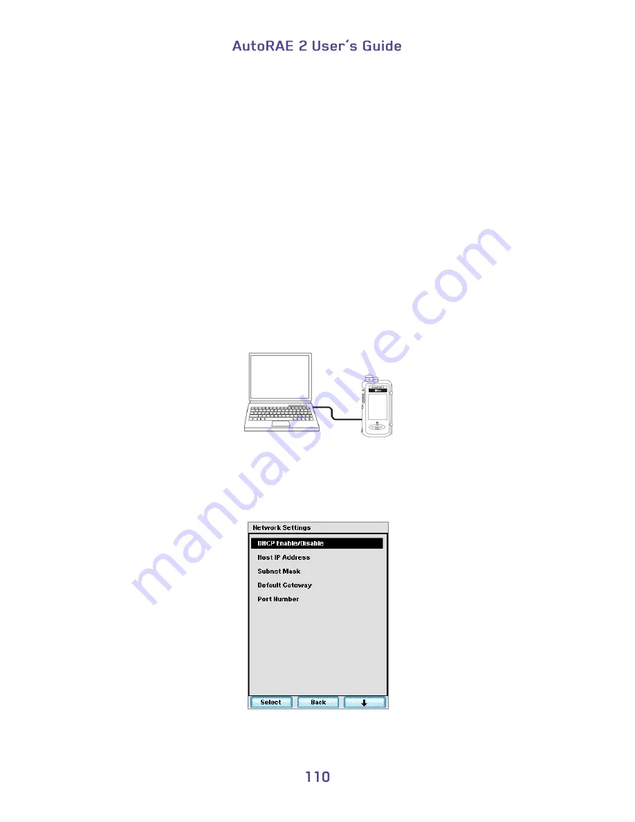
Connect an Ethernet cable between the PC and the AutoRAE 2 Controller.  


2.


On the AutoRAE 2 Controller, enter Function and then Settings choose “Select.” 

3.


When the dialog box appears, input your password. Select “Done.” 

4.


Now choose Network Settings and “Select” again. The first option is DHCP 
Enable/Disable (see Figure 1).  


Figure 1. AutoRAE2 Network Setting Menu. 

Содержание AutoRAE 2

Страница 1: ......

Страница 2: ...visiting www raesystems com support product registration By registering your product you can Receive notification of product upgrades or enhancements Be alerted to Training classes in your area Take a...

Страница 3: ...8 Performing A Calibration 31 9 Bump And Cal Error And Status Messages 32 10 Charging An Instrument s Battery 34 11 Removing An Instrument From A Cradle 34 11 1 AutoRAE 2 Reports 35 12 Programming A S...

Страница 4: ...Testing And Calibrating Via The Cradles Buttons 79 20 7 Configuration Settings 81 20 8 Settings 82 20 8 1 Gas Settings 85 20 8 2 System Settings 86 20 8 3 Network Settings 87 21 Programming An AutoRAE...

Страница 5: ...work Interface 110 24 2 Part Two Configure The WiFi Adapter Test The Network 111 25 Wall Mounting A Controller Cradles 116 26 Transferring Bump And Calibration Data 117 27 Maintenance 117 28 Technical...

Страница 6: ...f its life this product must undergo separate collection and recycling from general or household waste Please use the return and collection system available in your country for the disposal of this pr...

Страница 7: ...gement Deployable as a standalone cradle or a controller based system with up to 10 cradles Controller with a large color LCD display Up to 5 calibration gas cylinders can be connected at the same tim...

Страница 8: ...ttons Mode Y and N on the Controller 2 buttons Bump and Cal on each Cradle 2 buttons Bump and Cal Power supply 12V 7 5A output Charges up to 10 instruments at a time 12V 1 25A output Charges one instr...

Страница 9: ...radle 2 16 lbs 0 98 kg Handheld PID Cradle 2 79 lbs 1 27 kg MicroRAE Cradle 1 9 lbs 0 86 kg Terminal Adapter 0 33 lbs 0 15 kg Power Supply AutoRAE 2 Controller AC adapter 110V to 240V input 12V 7 5A o...

Страница 10: ...Regulator AutoRAE 2 Controller Demand flow regulator 0 to 1 000 psig 70 bar Cradle Same as above Pump Flow Rate AutoRAE 2 Controller Built in pump 500 ml min MultiRAE Cradle None relies on instrument...

Страница 11: ...onic and gas connections are automatically internally connected A controller based system can accommodate up to five distinct gas sources for multi sensor calibration and bump testing An AutoRAE 2 Cra...

Страница 12: ...AC adapter Air inlet hidden Filter hidden Sensors for testing ToxiRAE Pro LED alarms Sensor for testing ToxiRAE Pro buzzer Release mechanism Capture mechanism USB port not shown 2 character LED displa...

Страница 13: ...lter Sensors for testing QRAE 3 LED alarms Sensor for testing QRAE 3 buzzer Release mechanism Capture mechanism USB port not shown 2 character LED display Bump Status LED Bump key Charge contacts Char...

Страница 14: ...apter Air inlet hidden Filter hidden Sensors for testing LED alarms Sensor for testing buzzer Release mechanism Capture mechanism USB port not shown 2 character LED display Bump Status LED Bump key Ch...

Страница 15: ...that it extends 1 Turn the Handheld PID Cradle over 2 Remove the screw with the red washer 3 Pull out the capture mechanism until it is fully extended 4 Replace the screw Exhaust port 2 gas inlets DC...

Страница 16: ...ith Ports All Models The USB port has a sliding cover that protects the contacts from contamination when it is not in use Simply slide the cover over the port Gas ports USB port 12V DC power Input Exh...

Страница 17: ...E Pro models Handheld PID Cradle only comes with 1 Quick Connector P N T02 3301 000 4 screws and 4 screw covers to attach the right end cap to the Cradle if deployed in stand alone mode or Cradle to a...

Страница 18: ...nput side left end cap snaps on while the one on the other side right end cap gets slipped into its position and is then secured with two screws plastic caps are included to hide the screws Note The s...

Страница 19: ...from the AutoRAE 2 Controller and therefore does not need a separate AC adapter The jack for the AC adapter connection is in the recess of the left end cap Plug the barrel end of the AC adapter into t...

Страница 20: ...coal Filter When zeroing the ppbRAE 3000 it is necessary to use an external charcoal filter for the truest zero readings alternatively you can use ultra pure zero air It is also a good idea to use a c...

Страница 21: ...the port on the side of the AutoRAE 2 Cradle and the transformer end into an AC power source There is no power switch so when power is applied to the AC adapter the AutoRAE 2 Cradle is powered Cautio...

Страница 22: ...tion of the actual calibration gases connected to the Cradle match before you begin any bump test or calibration Cross Sensitivities Determine The Order In Which Sensors Should Be Calibrated Gases use...

Страница 23: ...d the NH3 sensor negative for some period of time After calibrating the Cl2 sensor return the instrument to clean air and wait until the most cross sensitive sensor NH3 fully recovers and or stabilize...

Страница 24: ...o the cradle face down making sure that it is aligned correctly with the contacts on the AutoRAE 2 Cradle s charging port There are two alignment points on one side and one alignment point on the othe...

Страница 25: ...s 6 6 1 Installing Adapters In The ToxiRAE Pro Cradle The two types of ToxiRAE Pro adapters are shown here Align the two holes in the appropriate adapter with the two matching ports inside the Capture...

Страница 26: ...e external filter on the instrument is not dirty or clogged and screwed onto the instrument inlet tightly 3 Make sure the monitor is either turned off or is in AutoRAE 2 Communications Mode 4 Place th...

Страница 27: ...ent into the cradle face down making sure that it is aligned correctly with the contacts on the AutoRAE 2 Cradle s charging port There are two alignment points on one side and one alignment point on t...

Страница 28: ...making sure that it is aligned correctly with the contacts on the AutoRAE 2 Cradle s charging port There are two alignment points on one side and one alignment point on the other side designed to mat...

Страница 29: ...RAE 3000 or UltraRAE 3000 into the cradle If the instrument does not have a Quick Connector P N T02 3301 000 already installed you must install one 6 9 1 Installing A Quick Connector MiniRAE Lite Mini...

Страница 30: ...or is in AutoRAE 2 Communications Mode 3 Place the instrument into the cradle face down making sure that it is aligned correctly with the contacts on the AutoRAE 2 Cradle s charging port There are two...

Страница 31: ...and initiates a warm up cycle to prepare the instrument for bump testing or calibration Note If the instrument s voltage is too low to power on the cradle initiates a warm up cycle until the voltage i...

Страница 32: ...for Bottles 15 and 16 under Gas Config 8 see Section 13 1 2 Insert an instrument in the AutoRAE 2 Cradle as described in Section 6 4 and wait for it to warm up as described in Section 6 5 3 When the...

Страница 33: ...he Cradle as specified for Bottles 15 and 16 under Gas Config 8 see Section 12 1 2 Insert an instrument in the AutoRAE 2 Cradle as described in Section 6 5 and wait for it to warm up as described in S...

Страница 34: ...ternation with Cal LED Red blinking in alternation with Bump LED Remove the instrument from the cradle and take the action indicated on the instrument s display Warm up completed successfully Green so...

Страница 35: ...ed in the instrument you may remove it from the Cradle and read its display for an error code If a Controller is used the Controller s display shows the error code Sleep mode Orange solid Orange solid...

Страница 36: ...ed 11 Removing An Instrument From A Cradle When you want to remove an instrument from a cradle press down on the red release lever until the capture mechanism springs forward releasing the instrument...

Страница 37: ...After you perform any test on an instrument the display on the instrument gives a report for each test that has been done Step through the screens to see results from tests that were performed For ex...

Страница 38: ...Select Exit to return the monitor to Normal Measurement Mode...

Страница 39: ...SB cable between a PC with ProRAE Studio II and the AutoRAE 2 Cradle 2 Make sure the AutoRAE 2 Cradle is on AC adapter connected and plugged in 3 Put the Cradle into PC communications mode Press and h...

Страница 40: ...s the AutoRAE 2 Cradle s configuration data a progress bar is shown during downloading The AutoRAE 2 Cradle s data is shown including its Model Number and Serial Number Click Clock Information to chec...

Страница 41: ...If you want to synchronize the date and time on the AutoRAE 2 Cradle with the time on the PC click the box labeled Sync with PC...

Страница 42: ...purge time and soak time for gas cylinders connected to each gas inlet You can modify these values and upload them to your AutoRAE 2 Cradle s or download the values currently programmed into the Crad...

Страница 43: ...When you click on Gas Config 8 the two gas bottles Gas Inlet 15 and Gas Inlet 16 are shown...

Страница 44: ...shows the selected Gas Bottle Gas Bottle 16 shown its Gas Number number of gases in the gas mix if the bottle contains more than one gas 4 gas mix shown Gas Lot Number and data that includes Gas Index...

Страница 45: ...18 CO2 3 SO2 11 Cl2 19 Isobutylene 4 NO 12 ClO2 20 Benzene 5 NO2 13 H2 21 Propane 6 HCN 14 HCHO 22 Methane 7 NH3 15 COCl2 23 Nitrogen 8 PH3 16 O2 24 ETO Note The currently selected Gas Index and name...

Страница 46: ...tration Unit menu select the desired gas concentration units there are other types of units ppm ppb mg ug LEL VOL CH4 12 6 Purge Time Sec Type to set the number of seconds for the system to purge with...

Страница 47: ...loading Individual Gas Inlet Settings If you only want to download a single set of Gas Inlet settings from the Cradle click the name Gas Inlet 4 for example and then click the Get Current Content Sett...

Страница 48: ...any settings modified or unmodified already in the active ProRAE Studio II session You may now modify or upload these settings 12 12 Uploading Settings To Multiple AutoRAE 2 Cradles You can apply set...

Страница 49: ...oRAE 2 Controller follow the AutoRAE 2 Controller Firmware Upgrade instructions on page 99 1 Download firmware from the RAE Systems web site or from a CD ROM 2 Connect a PC running ProRAE Studio II to...

Страница 50: ...9 Select the AutoRAE 2 Cradle 10 Click Select 11 The three options on the left are Setup Firmware and Tool Click Firmware...

Страница 51: ...ind and select the firmware file with a rfp extension 15 Click Open 16 Click Start 17 The firmware is uploaded to the AutoRAE 2 Cradle 18 Exit PC Communications mode on the AutoRAE 2 Cradle by pressin...

Страница 52: ...n instrument to a computer and firmware updates and configuration data can be uploaded to an instrument via the USB port on a stand alone AutoRAE 2 Cradle Use the included USB cable to connect the Aut...

Страница 53: ...s sources for multi sensor calibration and bump testing On Off switch Color LCD Fresh air inlet Gas ports USB to printer USB to PC RJ 45 Ethernet port 12V 7 5A DC power input On Off switch Alarm buzze...

Страница 54: ...000 12 volt 7 5A power supply P N 500 0141 000 with US P N 410 0036 000 UK P N 410 0036 004 and European P N 410 0036 005 power cords External inlet filters 1 installed three spare P N 008 3022 003 pa...

Страница 55: ...tandard SD card on which data are stored When one or more AutoRAE 2 Cradles are attached to the AutoRAE 2 Controller the AutoRAE 2 controller acts as the command center for the system The Controller p...

Страница 56: ...emble an AutoRAE 2 Controller Based System slide an AutoRAE 2 Cradle snugly against the AutoRAE 2 Controller If you have more than one AutoRAE 2 Cradle slide each one against the other until all are h...

Страница 57: ...ower is connected In addition three AA replaceable batteries in the AutoRAE 2 Controller maintain the last calibration record in the event that it is not written to the SD card 1 Make sure the AutoRAE...

Страница 58: ...air inlet on each attached cradle is disabled and air is taken in through the Controller s air inlet Therefore you only need to use one Active Carbon Filter for the Controller instead of on each cradl...

Страница 59: ...connection is in the recess on the left side of the AutoRAE 2 Controller next to the power on off switch Plug the barrel end of the AC adapter into the AutoRAE 2 and the transformer into an AC outlet...

Страница 60: ...ed The system performs a self test covering the AutoRAE 2 s internal pump and valves Terminal Adapter gas pressure in connected cylinders and other vital components and parameters As each cradle is po...

Страница 61: ...Manifold Check fails you should turn off the system and contact RAE Systems Technical Support If the Terminal Adapter Check fails make sure the Terminal Adapter is connected to the last AutoRAE 2 Crad...

Страница 62: ...s automatically as soon as their respective cradle has been powered up and identified by the AutoRAE 2 Controller 19 4 User Interface All functions and configurations are initiated by using the three...

Страница 63: ...warm up error or other error Warning Yellow Sensor does not match the gas Warm up None Instrument warm up Ready None Instrument ready to bump test or calibrate 19 6 Warm Up When you place a monitor in...

Страница 64: ...utoRAE 2 Controller is turned on it performs a self test SD card checks whether an SD card is present whether it is full or nearing full capacity etc a test of each attached AutoRAE 2 Cradle and then...

Страница 65: ...here is a mismatch check the instrument s settings in Programming Mode as well as the settings programmed for the AutoRAE 2 via ProRAE Studio II If all instruments in the cradles warm up and all test...

Страница 66: ...greater than 2GB but only 2GB of space will be used by the AutoRAE 2 Controller Note The SD card inside AutoRAE 2 can only be used for AutoRAE 2 recording Do not save other files to the SD card Althou...

Страница 67: ...cked SD Card If remaining space for data on the SD card is very low the display shows the message SD card running low on space If the SD card is full an error message appears on the display that says...

Страница 68: ...on the right Press until it locks into place making a click sound Slide the door up to cover the port 4 Insert and tighten the screw 20 1 2 Removing An SD Card To remove an SD card press in on it unt...

Страница 69: ...AutoRAE 2 Controller matches the type concentration of the actual calibration gas connected to it before you begin any bump test or calibration Also make sure the calibration gas is not past its due d...

Страница 70: ...u perform bump tests on individual instruments or all instruments that are cradled A bump test can be initiated by pressing a Bump button on the Cradle or selecting a Bump Test via the AutoRAE 2 Contr...

Страница 71: ...Note A grayed out box indicates that it cannot be selected When you check Bump All the Bump All checkbox and all of the other checkboxes for identified instruments are checked...

Страница 72: ...s Y to toggle the selection between checked and unchecked After you have made your selection s press MODE to start the bump test Press N to select Exit and then press Y to exit A screen shows the inst...

Страница 73: ...here is a mismatch between sensors and calibration gas settings then this message is shown The bump test countdown still proceeds The sensors that do match the calibration gas settings will be bump te...

Страница 74: ...t button during a bump test suspends the test and this message appears on the AutoRAE 2 Controller s display Removing an instrument from the cradle during a bump test interrupts it and results in the...

Страница 75: ...ss All sensors passed successfully Pass All sensors that were tested passed successfully but some sensors were not tested Fail The instrument failed one or more tests N A The instrument was not tested...

Страница 76: ......

Страница 77: ...tton on the Cradle or selecting a Calibration via the AutoRAE 2 Controller menus Press Y which selects Function A menu is shown with Bump Test at the top of the list already selected the triangle to t...

Страница 78: ...alibrate All box You can also select individual instruments for calibration Press N to scroll down the list Press Y to toggle the selection between checked and unchecked After you make your selection...

Страница 79: ...ountdown All calibrations are then performed automatically 20 5 1 Interrupting A Calibration Releasing an instrument from an AutoRAE 2 Cradle or otherwise interrupting a calibration suspends the test...

Страница 80: ...the instrument calibration cannot resume You must abort the calibration and restart it Press N to abort the calibration This screen is displayed After calibration is complete the AutoRAE 2 controller...

Страница 81: ...sing Y Report If an instrument does not pass calibration check the sensor s age and consult the instrument s User s Guide 20 6 Direct Bump Testing And Calibrating Via The Cradles Buttons When multiple...

Страница 82: ...e is no selection indicated You can start the bump tests and calibrations immediately by pressing Y Otherwise a countdown begins When it reaches zero the bump and calibrations are initiated You can qu...

Страница 83: ...ion Settings In addition to showing status of the most recent bump and calibration testing the main screen provides access to check settings and change the password At the main screen press Y which se...

Страница 84: ...0 8 Settings At the main screen press Y which selects Function A menu is shown Press N until Settings is selected the triangle to the right of the name indicates the selection Click Y to enter Setting...

Страница 85: ...n incorrect password The default value is 0000 four zeroes Press Y to increase a value 0 through 9 Press N to advance to the next digit Press MODE after you have entered the password If you enter an i...

Страница 86: ...ncorrect password again then you access the Basic settings which provides read only information about the gases configured for each gas inlet To navigate between the settings types in Advanced mode pr...

Страница 87: ...the gas configuration for each of the five gas inlets To advance through the settings press N The current screen is highlighted by the empty circle in the series of circles representing the five inlet...

Страница 88: ...he AutoRAE 2 Controller Model Serial Number Firmware Built Date You can set the date according to the format set in ProRAE Studio II Press Y to advance through numbers 0 through 9 Press N to advance t...

Страница 89: ...word New Password Press Y to advance through numbers 0 through 9 Press N to advance to the next digit Press MODE to save the new password Action after Bump Failed You can select the action performed b...

Страница 90: ...the window and return to the main menu Subnet Mask This is a read only screen that shows the Subnet Mask With Subnet Mask highlighted in the Network Settings menu press Y to access the Subnet Mask scr...

Страница 91: ...based system on a PC you need ProRAE Studio II Instrument Configuration and Data Management Software the AutoRAE 2 Controller based system connected to a power source and a USB PC communications cable...

Страница 92: ...roller s display shows this message while it is connected and communicating with a PC running ProRAE Studio II Communicating with Computer Please follow instructions in ProRAE Studio II Calibration an...

Страница 93: ...the left of the image of the AutoRAE 2 Controller Double click the AutoRAE 2 Controller to check its settings and to program it The Setup Firmware screen appears Notice that it shows the AutoRAE 2 co...

Страница 94: ...ramming This setup screen is shown Click Clock Information to check or set the time If you want to synchronize the date and time on the AutoRAE 2 Controller with the date and time on the PC click the...

Страница 95: ...Set the password for access to the AutoRAE 2 Note The default value is 0000...

Страница 96: ...ws the selected Gas Inlet Gas Inlet 1 shown its Gas Number number of gases in the gas mix if the cylinder contains more than one gas single gas shown Gas Lot Number Expiration Date and data that inclu...

Страница 97: ...g instruments using this gas 21 2 4 Gas Index You can use the pull down menus to select Gas Index values corresponding to the gas of interest Supported gases include 1 CO 9 HCl 17 CH3SH 2 H2S 10 HF 18...

Страница 98: ...of units ppm ppb mg m3 ug m3 LEL VOL CH4 21 2 8 Purge Time Sec Type to set the number of seconds for the system to purge with fresh air after performing a bump test or calibration 21 2 9 Soak Time Sec...

Страница 99: ...Individual Gas Bottle Settings If you only want to download a single set of Gas Bottle settings from the AutoRAE 2 click the name Gas Bottle 1 through 5 and then click the Get Current Content Settings...

Страница 100: ...erwrites any settings modified or unmodified already in the active ProRAE Studio II session You may now modify or upload these settings 21 7 Uploading Settings To Multiple AutoRAE 2 Systems You can ap...

Страница 101: ...Controller using ProRAE Studio II software running on a PC 1 Download firmware from the RAE Systems web site or from a CD ROM 2 Connect a PC running ProRAE Studio II to the AutoRAE 2 Controller via a...

Страница 102: ...oller 9 Click Select 10 The AutoRAE 2 Controller is shown along with its serial number Click Firmware 11 Double click on the AutoRAE 2 Controller s icon and this screen appears The options on the left...

Страница 103: ...are file with the rfp suffix Then click Upload Firmware 14 Click the box labeled Upgrade for specific SN and then pull down the menu and select the serial number that matches the one shown in the uppe...

Страница 104: ...ile is uploaded to the AutoRAE 2 Controller s SD card and the AutoRAE 2 Controller uploads the firmware to the AutoRAE 2 Controller or cradle respectively 19 Exit ProRAE Studio II on the PC 20 Disconn...

Страница 105: ...sting data from an AutoRAE 2 controller 1 Connect a USB cable to the AutoRAE 2 Controller and to a PC running ProRAE Studio II software 2 Make sure the AutoRAE 2 Controller has power and is turned on...

Страница 106: ...6 This screen appears 7 Expand either Online or Offline to view Instruments 8 Click Instruments...

Страница 107: ...Instruments that have been bump tested and calibrated on a system with this AutoRAE 2 Controller are shown...

Страница 108: ...9 Double click on an instrument to view its reports The Reports window opens for this instrument...

Страница 109: ...st in the left column If the list is long you can change the order so the list order is reversed from 001 002 003 etc to 003 002 001 etc Press one of these two buttons to change the sort order 12 Sele...

Страница 110: ...tion report Bump Test report Policy Violation report A typical bump or calibration report is shown in the right window 23 1 Exporting Reports The report can be exported for archiving or sending It can...

Страница 111: ...e changes you will see this prompt If you do not want to save changes to the configuration click No If you want to save the changes click Yes Select a name for the file which will be saved as a ProRAE...

Страница 112: ...1 8 1 Build 133 or newer AutoRAE2 controller firmware V1 20 or newer AutoRAE 2 Utility V1 02 Build 105 or newer Note This procedure has been tested with NetGear s WNCE2001 Universal Wi Fi Internet Ada...

Страница 113: ...the AutoRAE 2 Controller turn it off and on again 7 Set the corresponding PC Ethernet port IP address subnet mask and default gateway manually as shown in Figure 2 for connection to AutoRAE2 Figure 2...

Страница 114: ...as in Figure 3 for the WiFi Internet Adapter setup Also make sure the Obtain DNS server address automatically button is selected Figure 3 Set PC network properties to automatic for the WiFi Internet...

Страница 115: ...Figure 4 Select a wireless network This example shows all available wireless networks within range Your choices will be different Figure 5 Enter a password to access the selected wireless network...

Страница 116: ...eless network used is RAEGN as shown in Figure 4 10 There are two ways to connect using manual or automatic connection a Manually Open the corresponding TCP IP properties of the PC Wi Fi wireless port...

Страница 117: ...wirelessly connect to the AutoRAE 2 Controller 10 Run ProRAE Studio II which should be able to detect the AutoRAE 2 Controller via WiFi connection and communicate with the AutoRAE 2 Controller AutoRAE...

Страница 118: ...plywood or use other reinforcement for the wall Use a pair of slotted TS35 DIN rails 35mm high x 7 5mm deep cut to slightly longer than the length of the assembled system and attach to a strong wall o...

Страница 119: ...se and the dock area Do not use alcohol or solvents Inspect the ports in the dock and the space around and between the buttons and the case If dirt has settled into any of these places use a can of co...

Страница 120: ...ne 1 408 952 8260 Email training raesystems com Outside the Americas E Mail HZexpert honeywell com Honeywell Analytics Ltd 4 Stinsford Road Nuffield Industrial Estate Poole Dorset BH17 0RZ United King...

Страница 121: ......

Отзывы: