Page 10 of 22
IN052 Rev. K 0613
INSTALLATION INSTRUCTIONS
1
2
2.3. Plumbing Hook-up
All plumbing should be performed in accordance
with Local and State Codes by a Qualified Plumber.
1.
Shut off water main valve located after the pres-
sure tank.
2.
Drain water line.
3.
Plumb system into water line after the pressure
tank and all other water treatment equipment.
(Exception: Install before activated carbon filter/
tank.)
4.
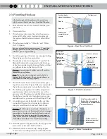
Plumb appropriately to “Water In” and “Water
Out”. (Figure 6)
For ease of installation and servicing a ¾” sharkbite
fitting is provided on the inlet. This is compatible
with 3/4” pex or copper tubing.
5.
From the open leg of the inlet tee run pipe/tubing
thru a bypass valve to a second tee.
6.
Plumb unit as shown in Figures 6, 7 and 7a. The
Bladder Tank must be connected to the Rise Leg
of the Tee provided on the System Outlet, without
any elbows between the Tee and Tank.
Warning: An undersized bladder tank will result in
premature pump failure.
Note: Pipe supports are required, particularly to
support the bladder tank. These are not shown, as
installation details vary by property.
7.
Plumb the water line to the house into the open
leg of the second tee. (Figure 7) It is recommended
that a flow control valve be installed in this line.
8.
The built-in pump pressure switch and pressure
regulator provided are designed for use with a
pressure tank. The pressure tank bladder pressure
should be set per the tank manufacturers recom-
mendations for a pressure switch setting of 37 psi.
9.
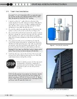
An outlet pipe must be installed in the overflow
connection (figure 6) and connected to drain or
sump in accordance to Local and State Codes.
Warning: Overflow may occur due to a blocked vent
pipe, debris in or wear of the solenoid valves, or incorrect
connection to the electrical supply. Failure to connect
the overflow to a drain or sump (with sump pump or
other means of external discharge) may flood the area
around the unit in the event of overflow occurring.
10.
With the system in bypass mode, slowly open the
main water valve and check for leaks.
11.
Remove tank cover and slowly change bypass
valve to service configuration and check for leaks.
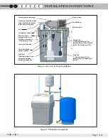
Figure 6 - Rear View, Unit Only
Figure 7 - Water Connections
Figure 7a - Water Connections
Overflow, connect to
drain or sump per local
and state codes
Outlet Tee provided with Unit.
Bladder Tank to be connected to
Tee Rise Leg. Do not install bends
between Tank and Tee.
Bladder tank
Minimum capacity
5 Gal. (Required)
Outlet valve
(Recommended)
Pressure gauge
(Optional)
Inlet valve
(Recommended)
Water out, to house
Flow control valve
(Recommended)
Bypass valve
(Recommended)
Existing house
pressure tank
(Tank tee, pressure switch,
pressure gauge and relief
valve not shown.)
Water in,
From well pump
Vent hole, breaks
siphon if unit overflows.
To bladder tank
Water in
Water out
Overflow, to be
connected to drain
or sump


