Page 12 of 22
IN052 Rev. K 0613
INSTALLATION INSTRUCTIONS
1
2
2.4. Electrical Hook-up
The Installation must comply with the National Electrical Code, NEC NFPA 70 and all applicable Local and
State Codes! Electrical Wiring must be completed by a qualified and licensed electrician.
1.
Turn main power switch, located on electrical box at rear left of unit, to the “Off” position.
2.
Bring power into the electrical box via the hole provided.
3.
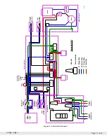
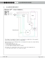
Connect power line to the connections provided within the electrical box per the Electrical Schematic
(Figure 8).
Warning: Line L1 must be connected to the switch connection. Do Not connect L1 to the white Neutral wire.
This will cause the Aeration System to malfunction.
4.
Ensure that the “red” lead, provided for an optional auxiliary fan, remains insulated if not used. The
“red” lead is the live feed from the Aeration System to the Fan.
Warning: Do Not connect any of the Fan Leads to a separate power source. This will cause the Aeration
System to Malfunction
5.
Connect power line to power source *. The AIRaider
™
EZ
95
System requires an 115VAC 20amp supply,
as marked on the system name plate, which is found on the rear left hand corner of the tank. Follow all
code requirements regarding wire and circuit breaker size.
* Manufacturer recommends that the AIRaider™ EZ
95
System be directly wired to the panel on a dedicated circuit.
WARNING: Never perform electrical work while standing in water. Do not attempt
wiring on a live circuit.
WARNING: Power Supply Voltage must match that marked on the System Name Plate.
Improper wiring may result in system and/or property damage.


