


en - Operating and Installation Instructions Q node 5
Operating and Installation Instructions Q node 5 - en
16 FOM5-00AM-DES-RNN5
V1.0 / 10.03.2015
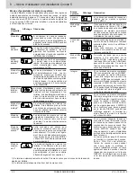
Error codes
An 'x' on error level 'b' and 'C' describes how often this error has
occurred. If a group error occurs more often than 9 times, a line '-'
is shown here.
Device itself
EA10
General device error
EA11
Hardware error
EA12
Memory error/loss of data
EA20
Parameters outside the tolerance limit
EA21
Main battery low
EA22
Backup battery low
EA30
Tolerance error of another system device
EA31
Primary address conflict (address assigned twice)
EA38 Clock error
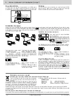
Other network
nodes
Eb1x Device error (hardware or memory)
Eb2x Battery too low or device outside tolerance
Eb3x
Errors 1 and 2 occurred
Eb4x Communication to network interrupted
Eb5x Errors 1 and 4 occurred
Eb6x Errors 2 and 4 occurred
Eb7x Errors 1, 2 and 4 occurred
Metering devices
EC1x Device error (hardware or memory)
EC2x Battery too low or device outside tolerance
EC3x
Errors 1 and 2 occurred
EC4x Communication to metering devices interrupted
EC5x Errors 1 and 4 occurred
EC6x Errors 2 and 4 occurred
EC7x Errors 1.2 and 4 occurred
IrDA-Master mode
Err1
Device is not supported
Err2
Device is not accepted
-
Lists are full e.g. more than 500 metering devices
-
External device supplying false data or error
Err3
Authorisation has failed.
-
External device waiting for correct login and password.
Err4
Break in communication
-
Connection interrupted before end of communication
Err5
Wrong configuration.
- Node still in idle mode
-
Pulse adapter not parameterised
-
External network nodes not in idle mode
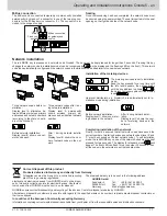
Acknowledging errors
After errors have been noted, they can be deleted by acknowledging
the error messages. To do this, change to the display level “E” by
pressing the blue DISPLAY key repeatedly. When the DISPLAY key
is kept pressed for more than two seconds, all the errors on the “EA”
level are deleted. If the error state occurs again, the error code will
reappear on the display.
Installation instructions
Installation location
The network nodes Q node 5 have only been designed for applica
-
tions inside buildings.
The type plate is on the inside of the device
cover.
Measures to avoid problems
Install the network node in a frost-free environment and not close to
high-voltage cables or electrical systems or on metallic or conduc
-
tive surfaces (read section 6.4 Brief installation instructions in the
system manual Q AMR before commissioning).
Silicone must not be used as an adhesive for gluing the Q node 5 in
place. If silicone is used as an adhesive for tiles etc., you must wait
for at least 24 hours after the use of the silicone before the Q node 5
may be installed.
Mechanical attachment Q node 5
The Q node 5 must be fixed to the wall using two screws. For this
purpose, two holes with a diameter of 6 mm must be drilled 184 mm
apart. Screws and dowels are included in the scope of supply.
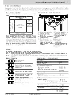
Commissioning Q node 5
For safety reasons, the Q node 5
is not delivered with the main bat
-
tery connected.
(1) Plug connector for voltage
supply DC 3.6 V
(2) Plug connector for backup
battery
(3) Main battery
(4) Backup battery
Start of service life calculation with a new battery:
After the network node has been fixed in place, the battery plug con
-
nector is inserted into the plug connector provided (1). The network
node display reads
. The operator then has to press the blue
DISPLAY button once in order to start the service life calculation for
the new main battery.
Caution:
It is possible to disconnect the main battery from the net
-
work node during operation and then to insert the connector again.
In this case, do not confirm by pressing the DISPLAY key – this
would result in the wrong remaining capacity display.
Changing the battery:
When a flat main battery is replaced,
the old battery is removed first and then the new one is inserted.
The operator then has to press the blue DISPLAY button once in
order to start the service life calculation for the new main battery.
The backup battery must not be disconnected at this point
since this would result in a loss of data.
Depassivation:
When the main battery is stored for longer periods,
particularly at storage temperatures higher than 30 °C, passiva
-
tion of the battery can occur. It is then no longer able to supply the
network node with sufficient energy. If the network node detects a
passivated battery, it automatically starts a depassivation cycle. This
is visualised by a flashing LED on the front. This process can take
several minutes. The network node then starts up in idle mode. If
the battery is cooled very heavily, this behaviour can also occur later
with other modes (e.g. installation mode).
Содержание RNN5
Страница 38: ...38 FOM5 00AM DES RNN5 V1 0 10 03 2015 Dimensions in mm...
Страница 39: ...V1 0 10 03 2015 FOM5 00AM DES RNN5 39 Test certificates in accordance with Tests and Criteria Manual...
Страница 40: ...40 FOM5 00AM DES RNN5 V1 0 10 03 2015 Test certificates in accordance with Tests and Criteria Manual...
Страница 41: ...V1 0 10 03 2015 FOM5 00AM DES RNN5 41...


