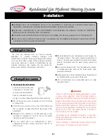
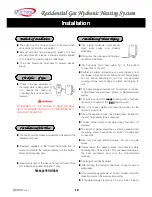
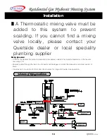

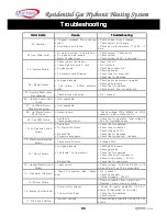

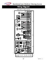
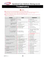


Residential Gas Hydronic Heating System
QVM 9
Series
24
24
24
24
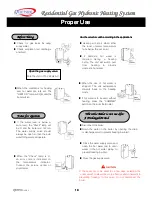
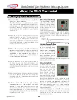
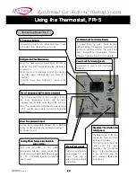
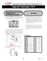
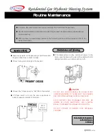
Using the Thermostat, FR-5
Using the Thermostat, FR-5
Using the Thermostat, FR-5
Using the Thermostat, FR-5
Power Switch and
Power Switch and
Power Switch and
Power Switch and Lamp(green)
Lamp(green)
Lamp(green)
Lamp(green)
The switch is used to turn the boiler
“
ON/OFF
”
.
Temperature Indicator
Temperature Indicator
Temperature Indicator
Temperature Indicator
Indicates the current room temperature and in case
of a malfunction, displays the error code.
Hot Water Switch and
Hot Water Switch and
Hot Water Switch and
Hot Water Switch and Lamp(Green)
Lamp(Green)
Lamp(Green)
Lamp(Green)
It is used when hot water only is required
without heating, for example, in summer and
the lamp indicates whether this switch has
been pressed(The temperature indicator,
however, indicates the room temperature).
Run(green) & Check(red) Lamp
Run(green) & Check(red) Lamp
Run(green) & Check(red) Lamp
Run(green) & Check(red) Lamp
When the heating water temperature function is
selected: The
“
ON
”
lamp indicates that the boiler is
in operation.
When the room temperature function is selected:
The
“
ON
”
lamp indicates that the boiler is in
operation.
Flickering check lamp indicates a failure in the
boiler.
Room Temperature Button and
Room Temperature Button and
Room Temperature Button and
Room Temperature Button and Lamp(green)
Lamp(green)
Lamp(green)
Lamp(green)
The unit runs according to the room temp. set by
the room temperature button and the lamp
indicates that the boiler is running at the set room
temp(The temperature of the heating water is set at
176
℉
and the temperature indicator indicates the
room temp.)
Room Temperature Control
Room Temperature Control
Room Temperature Control
Room Temperature Control
Set the room temperature between 55 to 88
℉
by
turning the dial(Selecting the temperature below
50
℉
stops the unit)
Energy
Energy
Energy
Energy Saving mode
Saving mode
Saving mode
Saving mode
The timer sets the stop
time between 0 to 4
hours. Turn dial to
select the appropriate
offset time.
Repetition Time Button and
Repetition Time Button and
Repetition Time Button and
Repetition Time Button and
Lamp(green)
Lamp(green)
Lamp(green)
Lamp(green)
The boiler stops for the time
set by the timer and then
runs for 20 minutes.
This button is to start this
cycle and the lamp
indicates this mode(The
temp. of the heating water
is set at 176
℉
and the
temp. indicator displays the
room temp).
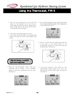
Thermostat Model FR-5
Heating Water Temperature Button &
Heating Water Temperature Button &
Heating Water Temperature Button &
Heating Water Temperature Button &
Lamp & Dial
Lamp & Dial
Lamp & Dial
Lamp & Dial
Unit runs according to hot water
temperature selected. Lamp shows that
mode is selected. Water temperature range
is 105
–
176 DEGF matched to type of
device used.


