background image

Installation and
Operating Manual

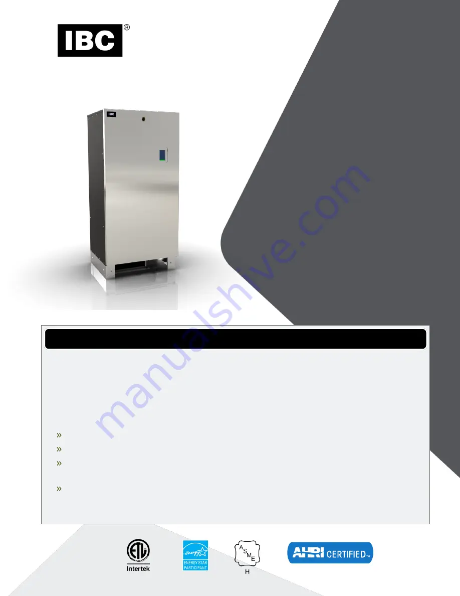
EX SERIES

Commercial Boilers

EX 700

EX 850

WARNING

If the information in this manual is not followed exactly, a fire or explosion may result causing
property damage, personal injury, or loss of life.

Do not store or use gasoline or other flammable vapors and liquids or other combustible
materials in the vicinity of this or any other appliance.

If you smell gas:

Do not try to light any appliance.

Do not touch any electrical switch; do not use any phone in your building.

Immediately call your gas supplier from a nearby phone. Follow the gas supplier’s
instructions.

If you cannot reach your gas supplier, call the fire department. Installation and service must
be performed by a qualified installer, service agency or the gas supplier.

Summary of Contents for EX Series

Page 1: ...apors and liquids or other combustible materials in the vicinity of this or any other appliance If you smell gas Do not try to light any appliance Do not touch any electrical switch do not use any pho...

Page 2: ...water volume system with a low hardness count may cause as much damage as a system with less volume and higher hardness so it is recommended to treat water so as to remove all dissolved solids Other...

Page 3: ...unit 15 3 2 1 Factors to consider for best installation conditions 16 3 3 Unpacking a boiler 17 3 4 Installation clearances 18 3 5 Exhaust venting and air intake venting 18 3 5 1 Code 19 3 5 2 Applic...

Page 4: ...60 4 0 About the boiler controller 61 4 1 Controller 61 4 2 Control interface 62 5 0 Before operating the boiler 63 5 1 Important pre ignition checks 63 5 1 1 Checklist for electrical conditions ducti...

Page 5: ...n 81 7 2 3 Air pressure sensor 81 7 2 4 Water pressure sensor 81 7 2 5 Gas pressure switches 82 7 2 6 Safety and Ignition Module SIM 82 7 3 Troubleshooting error messages 85 7 3 1 Touchscreen error me...

Page 6: ...Installation Commissioning Report 96 Boiler parts diagram 97 Revision history 101 4 Section Contents...

Page 7: ...e cases to death Keep instructions near the air handling unit for future reference Danger Do not store or use gasoline or other flammable vapors or liquids in the vicinity of this or any other applian...

Page 8: ...ding products and other similar products Chlorinated waxes or cleaners Chlorine based swimming pool chemicals Calcium chloride used for snow and ice clearing Sodium chloride or potassium chloride used...

Page 9: ...ater temp F C 34 1 34 1 Maximum water temp electronic hi limit F C 190 88 190 88 Max T supply return electronic fence F C 80 44 80 44 Max Water Temperature Lockout Limit F C 201 94 201 94 Power use 12...

Page 10: ...ef valves can be purchased 30 100 125 and 150 Table 1 Specifications Connection specifications The following table displays the required connection specifications for each model Flue Outlet 6 Schedule...

Page 11: ...Cabinet dimensions Figure 1 Frontal view Figure 2 Top view Figure 3 Back view 9 Cabinet dimensions...

Page 12: ...10 Section Specifications...

Page 13: ...n IBC s range of large commercial boilers is the solution for large scale projects such as apartment buildings office buildings big schools hospitals and hotels Figure 4 Front internal view Figure 5 B...

Page 14: ...trols Maximum allowable T 80 F 44 C 50 psi relief valve 345 kPa Boiler pump control up to H P 120V or 208 240V 1 2 Warranty IBC offers a 10 year warranty on the EX series heat exchanger and a 1 year w...

Page 15: ...l above carpeting At a new construction site or during renovations protect the boiler from drywall dust or other construction related contaminants Draw combustion air from a clean source e g outdoors...

Page 16: ...ate at a rooftop or sterile wall location Boiler condensate is corrosive Protective measures must be taken to prevent corrosion damage to metal roofs or other metal building components in contact with...

Page 17: ...dard for Controls and Safety Devices for Automatically Fired Boilers ANSI ASME CSD 1 If there is any conflict follow the more stringent regulations Conform to the current National Fuel Gas Code ANSI Z...

Page 18: ...uch as chlorinated and or fluorinated hydrocarbons can reduce the life of a boiler See list of Known contaminants on page 6 For this reason do not use the indoor air venting option using air surroundi...

Page 19: ...g Use the brackets provided to secure the boiler to the floor 3 3 Unpacking a boiler The boiler is shipped bolted to a pallet with four 4 anchor brackets and 3 8 Hex head bolts Once the anchor bracket...

Page 20: ...0 Table 4 Clearance distances for boiler mounting sites 3 5 Exhaust venting and air intake venting Warning Venting condensate drainage and combustion air systems for all IBC boilers must be installed...

Page 21: ...st be installed in accordance with the requirements of the jurisdiction having authority in Canada Part 8 Venting Systems of the B149 1 10 Code and any other local building codes are to be followed In...

Page 22: ...ical Close all building doors and windows such as doors adjacent to appliances remaining connected to the common venting system and other spaces of the building Turn on clothes dryers and any applianc...

Page 23: ...r ULC S636 Standard for Type BH Gas Venting Systems or stainless steel Type BH venting systems The vent temperature is limited by the boiler controller with the use of a flue temperature sensor to ens...

Page 24: ...the venting material Fully insert the approved venting material into the boiler s exhaust outlet and tighten clamp to ensure the venting connection is locked in place as shown below Figure 8 Securing...

Page 25: ...feet 120 6 x 5 30 90 Note Unused intake travel cannot be added to the exhaust Unequal intake and exhaust piping is allowed Exhaust venting must slope down towards the boiler with a pitch of at least...

Page 26: ...uction the installer must test the exhaust joints under fan pressure with the vent blocked using a soap and water solution the installer must fill the condensate trap prior to testing To drive the fan...

Page 27: ...ern about rain infiltration rain will drain away through the condensate trap Optional bird screen may be placed in a termination fitting Leave unglued and hold in place with a short nipple This permit...

Page 28: ...cally drained so it must be terminated with a down turned elbow as shown The intake pipe does not need to penetrate the roof at the same elevation as the exhaust as shown lower down on the roof is acc...

Page 29: ...st follow the installation instructions supplied with the venting material manufacturer Care must be taken to install the termination kit a minimum horizontal distance of 10 305 cm away from any porti...

Page 30: ...cm 1 30 cm B Clearance to window or door that may be opened 4 1 2 m below or to side of opening 3 91 cm C Clearance to permanently closed window 1In accordance with the current ANSI Z223 1 NFPA 54 Na...

Page 31: ...rance under veranda porch deck or balcony 12 30 cm 3 Table 6 Vent air inlet termination clearances Warning Important Maintain at least the minimum separation of exhaust vent termination from boiler in...

Page 32: ...Use a 45 elbow on the exhaust termination to launch the plume up and off the sidewall for protection of wall A short piece of venting cut at 45 gives a horizontal termination protected from wind loads...

Page 33: ...Figure 16 Sidewall vent termination configuration option 1 Figure 17 Sidewall vent termination configuration option 2 31 3 5 7 Sidewall vent termination...

Page 34: ...and the boiler should be isolated from interior dust sources Do not seal boiler case openings directly when firing allow for air circulation and ventilation in the immediate area Known Corrosive Conta...

Page 35: ...m Otherwise serious damage to the boiler may result Do not use bushing Flue gas exhaust to outdoors connection at rear of boiler Flue gas exhaust to outdoors Combustion air from outdoors Direct Vent i...

Page 36: ...r view combustion air intake Notes When installing air intake piping ensure that a trap is not formed in the piping causing a build up of water and blockage of intake air Such blockages will cause a b...

Page 37: ...t piping is allowed Ensure that adequate separation is maintained between the air intake inlet and the vent terminal Refer to the vent terminal configuration drawings in the Vent Termination section a...

Page 38: ...is not in a room adjacent to an outside wall air may be ducted from outside wall openings Provisions for combustion and ventilation air must be made as follows in the USA in accordance with the Nation...

Page 39: ...ires 1 Proper design and installation of exhaust venting to allow condensate to run back to the drain trap 2 Acid neutralization as appropriate To achieve these Allow a minimum per foot slope back to...

Page 40: ...ow The union nut must include an embedded O ring Ensure that the O ring seal is in place on the heat exchanger s stainless steel outlet tube 2 Attach the elbow and union nut firmly to the boiler s out...

Page 41: ...ondensate into building drain piping materials that are subject to corrosion use a neutralization package Warning After installing a condensate neutralization package the pH of the condensate discharg...

Page 42: ...fer to the neutralization instructions of the manufacturer Access to the discharge before the drain is necessary for proper maintenance in order to check the effectiveness of the neutralizing agent A...

Page 43: ...so it is recommended to treat water so as to remove all dissolved solids Other water chemistry allowable limits are as follows Acidity pH is to be between 6 6 and 8 5 Chloride is to be less than 125...

Page 44: ...col solutions are formulated to inhibit corrosion in hydronic heating systems of mixed materials Improper mixtures and chemical additives may cause damage to ferrous and non ferrous components as well...

Page 45: ...f a pipe size equal to or greater than that of the valve outlet 1 NPT Do not cap plug or obstruct the discharge pipe outlet 3 8 1 General piping best practices Primary secondary piping or the use of a...

Page 46: ...ng of boiler fluid and chemicals back into the system In buildings that may be unoccupied for long periods of time pressurization units are useful to prevent flood damage should leakage occur from any...

Page 47: ...cal and national codes System design is to be completed by an experienced hydronic designer or Engineer It is necessary to carefully read and follow these installation instructions along with the appl...

Page 48: ...w switch follow manufacturer s instructions Typical requirements include installing on a horizontal run with at least five 5 pipe diameters of straight piping both upstream and downstream of flow swit...

Page 49: ...ld be on the suction side of the circulator Primary pump or boiler circulator into connection at rear of boiler Fill station with isolation valve closed or fill tank Figure 25 Primary Secondary piping...

Page 50: ...ator Closely spaced tees to or from load 1 Closely spaced tees to or from load 2 Fill station with isolation valve closed or fill tank Dirt separator recommended Figure 26 Boiler trim options single b...

Page 51: ...ns between the fittings that would result in a pressure drop Heat migration On secondary loops that extend vertically to a load that is above the primary loop steps must be taken such as fabricating a...

Page 52: ...a mixing valve for simultaneous heating during higher temperature air handler operation Boiler can return to lower supply temperature when radiant alone is operating Figure 28 Primary Secondary pipin...

Page 53: ...DHW indirect tank Air handler Check valves may be integral to pumps not shown Figure 29 Two pump two load parallel piping concept 51 3 8 2 System piping...

Page 54: ...ng valves Check valve typical of each boiler may be integral to pump Tridicator shipped with boiler typical of each boiler Pressure relief valve shipped with boiler typical of each boiler Boiler pump...

Page 55: ...ler Boiler pump into rear connection typical of each boiler Low loss header hydraulic separator shown or closely spaced tees bridge to load piping Check valve for opt out circuit Opt out pump into rea...

Page 56: ...above the boiler s minimum specification at all firing rates and will not exceed the boiler s maximum pressure rating when locked up with no load 3 9 1 Gas pressure The boilers require a minimum inlet...

Page 57: ...ressure prior to reconnecting The boiler and its gas piping shall be leak tested before being placed into operation The gas valve is provided with pressure taps to measure gas pressure upstream supply...

Page 58: ...5 Amp fuses The maximum recommended load on each fuse is 4 Amps 80 of rating The maximum combined pump load is 10 Amps Isolation relays or contactors must be used if the loads exceed these maximums C...

Page 59: ...s and the boiler pump is 120V you can connect the black wire from the relay to the line voltage mains supplied to the boiler For 120 volt boiler pumps the black wire can be connected to the line volta...

Page 60: ...where you do not just pull the plug when done If a low airflow check vent error signal shows check for and remove any water in the clear vinyl air reference tubes This has been seen occasionally at c...

Page 61: ...ttom pair of contacts labeled External Control receives a 0 10VDC default or 4 20 mA signal from an external boiler controller for direct throttle control The boiler s own sensors act as high limits o...

Page 62: ...is not applicable with the EX modulating series boilers For a heat load where zone valves are used to manage thermostatically controlled zones each room s thermostat heat anticipator should be adjuste...

Page 63: ...loads Programmable setback override schedule The control can manage or operate in a network of up to 24 IBC boilers without additional controller Some of the new features available in the touchscreen...

Page 64: ...he screen active area and the boiler status bar All screens have an active area consisting of the screen title bar at the top and a border surrounding the active area At the bottom of the display ther...

Page 65: ...to shut off do not turn off or disconnect the electrical supply to the pump Instead shut off the gas supply at a location external to the appliance 5 1 Important pre ignition checks Once installation...

Page 66: ...all 1 8 or 3 mm flat screwdriver Connect a manometer and open the gas control valve Requirements are minimum 4 w c and maximum 14 w c Check that there are no gas leaks All connections are pressure tes...

Page 67: ...ir filter on page 76 As needed Inspect system for unusual noises Call your local heating contractor for service if needed As needed Keep vent terminals clear of obstructions snow dirt etc As needed In...

Page 68: ...sate trap Ensure that the trap has been re filled completely before firing boiler Bi monthly If condensate neutralization is used check the pH level of condensate discharge Annually 6 2 3 Burner Maint...

Page 69: ...ulfur Other fouling agents include airborne dust debris and volatiles With the burner removed examine the heat exchanger for signs of contamination and clean if necessary Refer to instructions in Repl...

Page 70: ...mage or leaks and repair as needed Annually Check the water pressure Pressure should be stable when the boiler is firing and the water temperature is rising If pressure rises sharply consider replacem...

Page 71: ...mental and toxicity reasons IBC recommends only using non toxic propylene glycol 6 2 10 Boiler treatment Maintenance for Boiler Treatment Frequency Check Check consistency of any boiler treatment used...

Page 72: ...ted tries fail to stop the leakage contact a licensed contractor or qualified service personnel to replace the valve While performing a try lever test a quantity of heat transfer fluid will be dischar...

Page 73: ...the boiler A ladder or step may be required to have a clear vertical view of the work area Do not attempt to reach from the front without a clear view as damage to connectors screws or refractory may...

Page 74: ...fore removing it from the fan Remove the six 6 6 mm screws to separate the mixing device from the fan 12 Attach the mixing device to the new fan 13 Re install the components in reverse order of the st...

Page 75: ...ed to have a clear vertical view of the work area Do not attempt to reach from the front without a clear view as damage to connectors screws or refractory may occur 5 Remove the screw and pull off the...

Page 76: ...76 or on the web at www cdc gov niosh 2 Wear long sleeved loose fitting clothing gloves and eyes protection 3 Assure adequate ventilation 4 Wash with soap and water after contact 5 Wash potentially co...

Page 77: ...fan to the heat exchanger lid An open ended wrench or socket is required 11 With the mixing device still attached remove the fan by pulling straight up ensuring that no wires are caught and that the...

Page 78: ...air filter should be inspected and or replaced monthly When replacing the air filter in the unit use a MERV 8 filter sized at 10 x 10 x 1 1 Remove the two screws of the air filter lid and set aside 2...

Page 79: ...rvice contractors should ensure that the end user is instructed on cleaning and refilling the trap Warning If condensate neutralization is used check the pH level of condensate discharge Never operate...

Page 80: ...ondensate trap to the top with water 5 Reinsert the condensate trap through the metal plate 6 Rotate the elbow and tighten the union nut so that elbow and condensate trap are secured Ensure the union...

Page 81: ...ry checks The first step in troubleshooting this system should be a review of the touchscreen controller There are a number of diagnostic features incorporated in the software that evaluate system int...

Page 82: ...y disconnecting their respective Molex connectors Place multi meter probes into the sensor s female Molex connector socket Do not apply voltage to the sensor as damage may result The supply water and...

Page 83: ...ough the combustion air intake or the exhaust vent becomes too restricted for safe operation the boiler will stop firing and display a Fan Pressure Error Also to prevent avoidable Fan Pressure Errors...

Page 84: ...djust the High or Low pressure switch If either the high or low gas pressure switch trips the boiler controller will show a Red bar at the bottom of the screen and indicate Low High Gas Pressure 7 2 6...

Page 85: ...uires a power cycle Table 11 SIM LED status Indicators 7 2 6 2 Low water cutoff function reset and test The low water cutoff LWCO function provides continuous protection against a low water incident I...

Page 86: ...rs the hi limit temperature set in the SIM If the water temperature exceeds the hi limit temperature the boiler goes into a lockout condition locks requiring a manual reset You can test the hi limit c...

Page 87: ...n 7 3 Troubleshooting error messages Errors shown on the touchscreen controller are described below as well as diagnoses and fixes 7 3 1 Touchscreen error messages Warning Never attempt to repair the...

Page 88: ...ion probe rods is too large or too small Adjust ignition probe rod gap between and 3 16th 3 2 4 7 mm Spark but no ignition Check spark module is sending power to gas valve close gas supply then discon...

Page 89: ...Hi Limit cutoff temperature Error Issue Diagnosis Fix Error Water High Limit Exceeded Water temperature exceeds hi limit Boiler is in hard lockout mode See Water Temperature function reset and test on...

Page 90: ...back of the controller board Unknown Error The sensor plug is not engaged Check the P501 plug is fully engaged in the back of the controller board Temperature sensor input problem Test each temperatu...

Page 91: ...is dry by re running post purge otherwise clean or replace igniter probe Boiler rumbles when igniting Fluctuating gas pressure gas pressure too high too low Check CO2 level via analyzer Check for pro...

Page 92: ...level Defective thermostat Refer to manufacturer s instructions Obstruction in condensate drain Inspect and clean condensate drain Unit cycling on operating safety controls Check operation with Ohmmet...

Page 93: ...Water Cutoff won t clear Boiler is in 1 hour safety lockout Reset safety device and cycle boiler power off and on to reset error DHW taking too long to heat Sensor may be under reading actual water t...

Page 94: ...ired Confirm adequate pump size and temp rise in the heat exchanger Slow combustion air blower Check that CO2 level is within specification Dirty burner heat exchanger Check pressure drop Low water fl...

Page 95: ...Appendices Wiring diagrams Figure 39 Controller electrical diagram 93 Appendices...

Page 96: ...Figure 40 Internal wiring diagram 94 Section Appendices...

Page 97: ...Figure 41 Sequence of Operation 95 Wiring diagrams...

Page 98: ...____________ System Filled type concentration of any glycol chemicals used _________________________ Air purge completed Relief Valve correctly installed and piped Relief valve try lever test performe...

Page 99: ...gnition Module 500 105 P 270 40 Top panel 251 030 P 1227 50 Controller module chassis 251 042 P 1228 60 Gas valve relay 240 165 P 1233 70 Boiler pump relay 240 165 P 1233 80 Transformer 240 008 P 9059...

Page 100: ...er Description Part Number Replacement Kit Numbers Wiring harness not shown P 1232 Item Number Description Part Number Replacement Kit Number 150 Fan 240 156 P 1212 160 Fan gasket 255 126 98 Section A...

Page 101: ...16 210 Heat exchanger gasket 255 125 P 1222 220 Refractory 255 123 P 1218 230 Burner 180 270 P 1224 240 Burner gasket 255 128 P 1223 250 Heat exchanger 700 170 046 P 1230 Heat exchanger 850 170 047 P...

Page 102: ...t off probe 240 143 P 9078 360 Supply Water temperature sensor 240 159 P 1225 370 Tridicator field installed 180 283 P 1234 380 Relief valve field installed 180 279 P 1205 390 Air pressure sensor 240...

Page 103: ...Revision history R0 September 2019 Initial release R1 December 2019 Measuring the inlet gas pressure Resetting the High Low pressure switches new drawing Fig 23...

Page 104: ...IBC Technologies Inc 8015 North Fraser Way Burnaby BC Canada V5J 5M8 Tel 604 877 0277 Fax 604 877 0295 Toll Free 1 844 432 8422 www ibcboiler com January 2020 IBC Technologies Inc 2020 120 327 R1...

Reviews: