background image

MFC Series Boilers User Manual


OMM-0104_94 


AERCO International, Inc. 

 100 Oritani Dr. 

  Blauvelt, NY 10913  

 Page 

1

 of 

170


GF-146 


 Ph.: 800-526-0288  

 12/29/2015 


USER MANUAL 

Installation, Operation and Maintenance of: 
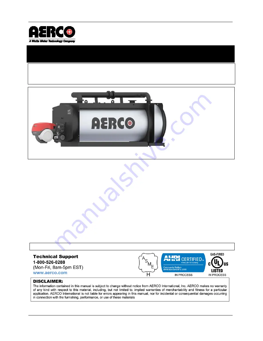
MFC Series 

Multi-Fuel Condensing Boilers


                                                   MFC 10000 

Applies to MFC Series Models: 

  MFC 3000 

  MFC 4000 

  MFC 5000 

  MFC 6000 

  MFC 8000 

  MFC 10000 

NOTE:

  Refer to the AERCO 

MFC Series Installation  Manual, GF-146-IN

, for preliminary 

assembly and installation instructions and information. 

Latest Update: 12/29/2015  


Summary of Contents for MFC 10000

Page 1: ...USER MANUAL Installation Operation and Maintenance of MFC Series Multi Fuel Condensing Boilers MFC 10000 Applies to MFC Series Models MFC 3000 MFC 4000 MFC 5000 MFC 6000 MFC 8000 MFC 10000 NOTE Refer to the AERCO MFC Series Installation Manual GF 146 IN for preliminary assembly and installation instructions and information Latest Update 12 29 2015 ...

Page 2: ...9 3 3 3 3 4 Installation Site 20 3 5 Boiler Room 20 3 6 Flue 21 3 7 Water Connections 21 3 8 Sealed Hot Water Heating System w Expansion Vessel 21 3 9 Electrical Connections 22 3 10 Burner Door Opening Orientation 23 3 11 Reversing the Opening Direction of the Burner Door 23 3 12 Adjusting the Boiler Door Vertical and Horizontal 26 SECTION 4 STARTUP 28 4 1 Preliminary Checks 28 4 2 Water Treatment...

Page 3: ... 53 SECTION 7 MFC 3000 NATURAL GAS ONLY BURNER 54 7 1 Combustion Head Adjustment 57 7 2 Gas Supply Pressure 59 Figuring Burner Output 60 7 2 1 Figuring Required Burner Output 61 7 2 2 7 3 Adjustments Before First Firing Gas 62 7 4 Startup for MFC 3000 Gas Only Burner 64 Gas Air Delivery Adjustment 65 7 4 1 Air Pressure Switch Adjustment 66 7 4 2 Maximum Gas Pressure Switch Adjustment 67 7 4 3 Mini...

Page 4: ... Air Adjustment 99 9 4 1 Gas Air Delivery Adjustment 99 9 4 2 Air Fuel Control and Power Modulation System 100 9 4 3 9 5 Final Calibration of the Pressure Switches 101 Air Pressure Switch Adjustment 101 9 5 1 Maximum Gas Pressure Switch Adjustment 102 9 5 2 Minimum Gas Pressure Switch Adjustment 102 9 5 3 9 6 Final Checks with Boiler in Operation 103 SECTION 10 MFC 8000 10000 DUAL FUEL BURNER 104 ...

Page 5: ...0 Gas Only Burner 132 Burner Firing 133 11 7 1 Combustion Air Adjustment 133 11 7 2 Gas Air Delivery Adjustment 133 11 7 3 Air Fuel Control and Power Modulation System 134 11 7 4 11 8 Final Calibration of the Pressure Switches 135 Air Pressure Switch Adjustment 135 11 8 1 Maximum Gas Pressure Switch Adjustment 136 11 8 2 Minimum Gas Pressure Switch Adjustment 136 11 8 3 11 9 Final Checks with Boil...

Page 6: ...Pump 144 13 6 1 Filters 144 13 6 2 Nozzles 144 13 6 3 Flexible Hoses 144 13 6 4 Fuel Tank 144 13 6 5 Combustion 144 13 6 6 13 7 Gas Operation MFC 8000 10000 Only 144 Gas Leaks 144 13 7 1 Gas filter 145 13 7 2 Combustion 145 13 7 3 APPENDIX A OPERATIONAL SEQUENCE DIAGRAMS 146 13 8 MFC 3000 6000 Sequence of Operation Diagram 146 13 9 MFC 8000 10000 Sequence of Operation Diagram 147 APPENDIX B ELECTR...

Page 7: ...000 800 000 4 000 000 3 420 000 3 800 000 MFC 5000 1 000 000 5 000 000 4 275 000 4 750 000 MFC 6000 1 200 000 6 000 000 5 130 000 5 700 000 MFC 8000 1 600 000 8 000 000 6 840 000 7 600 000 MFC 10000 2 000 000 10 000 000 8 550 000 9 500 000 Output based on a supply temperature based 80 F incoming water with a 20F rise Whether used in singular or modular arrangements the MFC Series offers the maximu...

Page 8: ... an integral part of the product and must be maintained in legible condition It must be given to the user by the installer and kept in a safe place for future reference WARNING Do not use matches candles flames or other sources of ignition to check for gas leaks Fluids under pressure may cause injury to personnel or damage to equipment when released Be sure to shut off all incoming and outgoing wa...

Page 9: ...more perform the following procedure Shutting Boiler Down for Extended Period 1 Set ON OFF switch on the front panel to the OFF position to shut down the boiler s operating controls 2 Disconnect AC power from the unit 3 Close the water supply and return valves to isolate boiler 4 Close external gas supply valve 5 Open relief valve to vent water pressure To bring the boiler back into service after ...

Page 10: ...is to be installed In addition the installing plumber or gasfitter shall observe that a battery operated or hard wired carbon monoxide detector with an alarm is installed on each additional level of the dwelling building or structure served by the side wall horizontal vented gas fueled equipment It shall be the responsibility of the property owner to secure the services of qualified licensed profe...

Page 11: ...ion of the venting system design or the venting system components and 2 A complete parts list for the venting system design or venting system d MANUFACTURER REQUIREMENTS GAS EQUIPMENT VENTING SYSTEM NOT PROVIDED When the manufacturer of a Product Approved side wall horizontally vented gas fueled equipment does not provide the parts for venting the flue gases but identifies special venting systems ...

Page 12: ...higher temperature applications when necessary but allows for the building to reset water temperature for condensing in the shoulder months 2 2 Certification References and Compliance Each boiler and Stainless Steel 4th Pass is provided with a manufacture plate that can be found in the envelope with the boiler documents The plate lists Manufacturer Plate Information BOILER STAINLESS STEEL 4TH PASS...

Page 13: ...0 GPM 1 3 PSIG 500 GPM 1 9 PSIG 600 GPM 1 1 PSIG 800 GPM 1 7 PSIG 1000 GPM Turndown Natural Gas Propane Up to 5 1 20 Turndown 2 Fuel Oil Progressive Vent Air Intake Connections 10 Inch 12 Inch 12 Inch 14 Inch 16 Inch 16 Inch Vent Materials AL29 4C Type of Fuel Natural Gas Propane 2 Fuel Oil backup NOx Emiss 30ppm Capab on Nat Gas Yes Temperature Control Range 80ºF to 230ºF Ambient Temperature Rang...

Page 14: ... 0 0 6 18 1 6 5 27 6 6 9 27 2 MFC 4000 58 7 170 1 88 3 66 1 129 0 7 3 75 4 4 5 16 2 36 2 76 2 48 9 3 4 0 5 17 3 6 4 27 4 6 9 29 3 MFC 5000 58 7 182 3 88 3 66 1 141 2 7 3 75 4 4 5 16 2 36 2 76 2 49 3 3 4 0 5 17 3 6 4 35 6 6 9 29 3 MFC 6000 70 9 185 0 101 1 76 8 143 8 8 5 87 1 3 1 22 8 40 9 86 8 50 8 4 4 1 1 21 1 6 6 53 2 6 7 35 4 MFC 8000 70 9 216 3 102 3 76 8 163 5 8 5 87 1 7 8 22 8 40 9 86 8 53 8...

Page 15: ...completeness at the time of receipt from the carrier and before the bill of lading is signed 3 2 Moving Unpacking the Unit While packaged in the shipping container the unit can be moved using a forklift Refer to the chart above in order to properly size forklift or other necessary equipment that may be required in order to move the unit Carefully unpack the unit taking care not to damage the unit ...

Page 16: ...TER 3 INSTALLATION Page 16 of 170 AERCO International Inc 100 Oritani Dr Blauvelt NY 10913 OMM 0104_94 12 29 2015 Ph 800 526 0288 GF 146 Table A MFC Series Accessories Refer to the MFC Boiler Field Assembly TID 0164 for more information ...

Page 17: ... 1 4 CONNECTION PIPE REAR 1 5 EXPANSION JOINT 1 6 SCREW 32 7 NUTS 32 8 CONNECTION PIPE GASKETS 4 9 ELBOW 2 10 BOILER DRAIN PIPE 1 11 BOILER DRAIN PIPE 1 12 THERMOINSULATING MATERIAL KIT FOR BURNER HEAD 1 13 SCREW BETWEEN STAINLESS STEEL 4TH PASS AND BOILER 9 14 LARGE WASHERS BETWEEN STAINLESS STEEL 4TH PASS AND 9 15 CONN PIPE SUPPORT 2 16 SCREWS 4 17 NUTS for CONN PIPE 4 18 LOCK WASHERS for CONN P...

Page 18: ...el Gas Oil Power Requirements Amperage MFC Burner 208 3 60 460 3 60 575 3 60 3000 RLS120 20 0 15 0 15 0 4000 RLS160 30 0 15 0 15 0 5000 RLS160 30 0 15 0 15 0 6000 RLS160 30 0 15 0 15 0 8000 RLS300 40 0 20 0 15 0 10000 RLS300 40 0 20 0 15 0 Gas Burner Power Requirements Amperage MFC Burner 208 3 60 460 3 60 575 3 60 3000 RS70 15 0 15 0 15 0 4000 RS100 15 0 15 0 15 0 5000 RS130 15 0 15 0 15 0 6000 R...

Page 19: ...nimum front door clearances are required MFC 3000 80 2032 mm MFC 4000 5000 92 2336 8 mm MFC 6000 10000 133 3378 2 mm SIDES 24 inches 610 mm REAR 24 inches 610 mm TOP 12 inches 457 mm from top of secondary inlet high temp pipe connection NOTE MFC Series boilers may be installed side by side with a minimum 6 side clearance as long as there is access to the rear of the units Note the necessary burner...

Page 20: ...llation must comply with all requirements specified in Chapter 1 Safety Precautions 3 4 Installation Site Before connecting the boiler perform the following operations Thoroughly clean all the system pipes in order to remove any foreign matter that could affect correct operation of the boiler Check that the flue has an adequate draught that there is no narrowing of passages and that it is free fro...

Page 21: ...ter contained in the heating system increases in pressure during operation ensure that its maximum value does not exceed the maximum hydraulic pressure specified on the component rating plate Ensure that the safety valve outlets of the boiler and hot water tank if any have been connected to an exhaust funnel in order to prevent the valves from flooding the room if they open Ensure that the pipes o...

Page 22: ...R DEVICES SHOULD BE ON THE SAME ELECTRICAL CIRCUIT AS THE BOILER A three pole switch must be installed on the electrical supply line in an easily accessible location to quickly and safely disconnect electrical service DO NOT attach the switch to sheet metal enclosures of the unit After placing the unit in service the ignition safety shutoff device must be tested If an external electrical power sou...

Page 23: ...from the left with functioning hinges on the right Figure 3 4 Factory Installed Burner Door Hardware Configuration 3 11 Reversing the Opening Direction of the Burner Door Since there are already integral hinges on both sides of the door the only procedures necessary to reverse the opening direction is to reverse the left and right side door fixing hardware and then to ensure a tight seal and prope...

Page 24: ...procedure if needed See Section 3 5 for more information about adjustments if needed NOTE The main barrel nuts on the front should be switched in a X pattern with one opening side and one hinge side nut always completely secured Start by reversing the upper left open side bolt with the lower right hinge side nut as shown in Figure 3 5 WARNING NEVER REMOVE ALL FOUR BARREL NUTS AT THE SAME TIME Figu...

Page 25: ...ow tighten the hinge side nut in the upper left position completely with the wrench Figure 3 8a Hinge Nut to Upper Left Figure 3 8b open Side Nut to Lower Right 8 Perform the same procedure above only by reversing the lower left opening side nut with the upper right hinge side nut as illustrated in Figure 3 9 CAUTION When cross changing the barrel nuts always make sure that the other two barrel nu...

Page 26: ... seating over the boiler opening properly or if there are problems inserting the barrel nuts over the hinge bolts perform the following Adjusting the Boiler Door Vertical Adjustment 1 Determine which hinges need adjustment 2 With the door ajar loosen the vertical adjustment locking nuts of the hinge 3 Adjust the vertical adjustment nut as required to raise or lower the hinge bolt 4 When satisfied ...

Page 27: ...ease the distance the hinge joint projects into the door opening 3 When satisfied with the adjustment retighten the locking nut 4 Check the proper adjustment in depth ensuring that the door manually pushed up to the stop plate naturally returns to the slightly ajar position This is to ensure the hinge side door seal Figure 3 12 Adjusting Horizontal Adjustment Nut on Hinge For any problems related ...

Page 28: ...henomena that occur in heating systems are described below Scaling 4 2 1 Scale reduces heat transfer between the combustion gases and the water causing an abnormal increase in the temperature of the metal and therefore reducing the life of the boiler Scale is found mostly at the points where the wall temperature is highest and the best remedy at construction level is to eliminate areas that overhe...

Page 29: ...volved Filling times vary depending on the capacity and characteristics of the system In the case of a sealed system with an expansion vessel water is let in until the pressure gauge indicator reaches the static pressure value pre set in the vessel Heat the water to maximum temperature During this operation the air contained in the water is released through the automatic air separators Once the ai...

Page 30: ... sized for the maximum flow rate necessary for the boiler and that it is provided with all control and safety devices provided for by the regulations referred to above In particular when using gas o Check that the gas supply pipe complies with the regulations in force o Check that all the gas connections are sealed o Check that the boiler room vents are of sufficient size to ensure the air flow di...

Page 31: ...ctions should be used CAUTION It is advisable to replace nozzles every year during regular maintenance operations WARNING The use of nozzles other than those specified by the manufacturer and the inadequate regular maintenance of the boiler may result in emissions exceeding the limits set forth by the regulations in force and can pose a potential serious hazard to people and property The manufactu...

Page 32: ...TER 6 MFC 3000 DUAL FUEL BURNER Page 32 of 170 AERCO International Inc 100 Oritani Dr Blauvelt NY 10913 OMM 0104_94 12 29 2015 Ph 800 526 0288 GF 146 6 1 MFC 3000 Dual Fuel Burner Features Figure 6 1 MFC 3000 Dual Fuel Parts and Features ...

Page 33: ...ssembly with pressure regulator on nozzle return 18 Gas pressure test point and head fixing screw 19 Air pressure test point 20 Air servomotor 21 Pumpmotor 22 Low oil pressure switch 23 Pilot attachment 24 Pump 25 Gastrainflange 26 Boiler mounting flange 27 Flame stability disk 28 Screw securingfantosleeve 29 Max gas pressure switch 30 Ignition transformers T2 for gas operation 31 Lifting rings an...

Page 34: ...bly 6 2 2 In order to assemble the nozzle proceed as follows Assembling the Nozzle 1 Remove the screw 1 as shown in Figure 6 2 2 Remove the nozzle assembly 2 per the arrows in Figure 6 2 Figure 6 2 Nozzle Assembly Steps 1 and 2 3 Install the nozzle 1 per Figure 6 3 Figure 6 3 Nozzle Assembly Step 3 Figure 6 4 Nozzle Assembly Step 4 4 Fit the wrench through the central hole in the flame stability d...

Page 35: ...rding to the fuel pressure on the nozzle return The chart in Figure 6 5 shows this relationship for type A4 return flow nozzles with a pump delivery pressure of 290 PSI The horizontal axis in the chart represents the PSI Nozzle Return Pressure and the vertical axis the GPH Nozzle Flow Rate The values indicated in the right side of Figure 6 5 refer to the data printed on the nozzle With a pump deli...

Page 36: ...the eccentric 6 is possible when its operation field matches the servomotor operation field 0 90 so that every variation of the servomotor position corresponds to a pressure variation If pressure fluctuations are detected on the gauge 1 see Figure 6 6 at the maximum capacity of the nozzle maximum pressure in the return line slightly decrease the pressure in the return line until fluctuations are c...

Page 37: ...ning 2 Insert the ignition electrode cables 3 Remove the extension bars 31 shown in Figure 6 1 4 Slide the burner up to the sleeve so that it is positioned as shown in Figure 6 8 5 Refit screws 2 shown in Figure 6 8 on slide bars 3 including the safety plate 15 per Figure 6 9 6 Secure the burner to the sleeve by tightening screws 1 shown in Figure 6 8 7 Connect the oil pipes again by screwing on t...

Page 38: ...o the pump seal will occur immediately if it is run with the return line closed and the by pass screw inserted Remove the plugs from the suction and return connections of the pump Connecting the Hydraulics 1 Insert the hose connections with the supplied seals into the connections and screw them down See Figure 6 10 2 Take care that the hoses are not stretched or twisted during installation 3 Insta...

Page 39: ...ine could cause the seal located on the pump shaft to break The time required for this operation depends upon the diameter and length of the suction tubing If the pump fails to prime at the first starting of the burner and the burner locks out wait approximately 15 seconds reset the burner and then repeat the starting operation as often as required After 5 or 6 starting operations then allow 2 or ...

Page 40: ...he following diagram is used to calculate manifold pressure taking into account combustion chamber pressure Figure 6 12 Burner Output Diagram Gas manifold pressure measured at test point per 1 shown in Figure 6 13 with Combustion chamber at 0 W C Burner operating at maximum output Combustion head adjusted as indicated in diagram shown in Figure 6 15 Figure 6 13 Gas Manifold Pressure Measuring Loca...

Page 41: ...re measured at test point 1 shown in Figure 6 13 2 Find the nearest pressure value to your result in Figure 6 12 3 Read off the corresponding output on the left EXAMPLE Maximum Output Operation Natural Gas Gas pressure at test point 1 per Figure 6 13 4 41 WC Pressure in combustion chamber 0 79 WC 4 41 0 79 3 62 W C A maximum output of 3616 MBtu hr shown in the table below corresponds to 3 62 WC pr...

Page 42: ... not clogged The setting of the combustion head depends on the maximum output of the burner Adjusting the Combustion Head Turn screw 6 shown in Figure 6 14 until the notch shown in Figure 6 15 is level with the front surface of the flange 5 Figure 6 14 Combustion Head Setting EXAMPLE Maximum burner delivery 23 1 GPH The chart shown in Figure 6 15 indicates that for this delivery the combustion hea...

Page 43: ...djusted if required after the burner has been ignited The only operation required in this phase is the application of a pressure gauge on the appropriate pump attachment 6 11 Air Damper Adjustment The first time the burner is fired leave the factory set low and high fire settings unchanged 6 12 Ignition Pilot Adjustment Position the pilot and electrode using the dimension shown in Figure 6 16 The ...

Page 44: ...d out the supply line vent operations eliminating air or inert gases from the piping 2 Slowly open the manual valves situated upstream of the gas train 3 Adjust the minimum gas pressure switch shown in Figure 6 17 to the start of the scale Figure 6 17 Minimum Gas Pressure Switch 4 Adjust the maximum gas pressure switch shown in Figure 6 18 to the end of the scale Figure 6 18 Maximum Gas Pressure S...

Page 45: ...he air from the gas line 7 Fit a U type manometer shown in Figure 6 20 to the gas pressure test point on the sleeve The manometer readings are used to calculate the MAX burner power using the diagram in Figure 6 12 Figure 6 20 Manometer Insertion Point NOTE Before starting up the burner it is good practice to adjust the gas train so that ignition takes place in conditions of maximum safety i e wit...

Page 46: ...ructions to perform this operation 3 Turn the switch to the ON position shown in Figure 6 21 and turn the switch of to position LOCAL and turn the switch to position OIL for oil operation and GAS for gas operation Figure 6 21 Burner Controls Used for Startup DANGER Make sure that the lamps or testers connected to the solenoids or indicator lights on the solenoids themselves show that no voltage is...

Page 47: ...supply Gas Air Delivery Adjustment 6 14 1 Adjusting Gas Air Delivery 1 Slowly open butterfly gas valve to maximum open position 2 Adjust the required maximum output with the gas pressure stabilizer 3 Adjust the combustion parameters with the air servomotor and store the maximum combustion point 4 Complete the procedure by synchronizing the combustion with the two servomotors and storing the differ...

Page 48: ...fan Adjust the air pressure switch shown in Figure 6 22 after having performed all other burner adjustments with the air pressure switch set to the minimum scale position Adjusting the Air Pressure Switch 1 With the burner operating at low fire adjust the pressure switch by slowly turning the relative knob clockwise until the burner locks out 2 Then turn the knob counter clockwise about 20 of the ...

Page 49: ... of the scale Adjusting Maximum Gas Pressure Switch 1 With the burner operating at MAX output reduce the adjustment pressure by slowly turning the adjustment dial anticlockwise until the burner locks out 2 Then turn the dial clockwise by 0 8 WC and repeat burner firing 3 If the burner locks out again turn the dial again clockwise by 0 4 W C Figure 6 24 Maximum Gas Pressure Switch Minimum Gas Press...

Page 50: ... Low Oil Pressure Switch 6 14 6 The low oil pressure switch is factory set to 261 PSI 18 bar If the oil pressure goes down this value in the delivery piping the pressure switch stops the burner Burner starts again automatically if the pressure goes above 261 PSI 18 bar after burner start up High oil pressure switch 6 14 7 The high oil pressure switch is factory set to 43 5 PSI 3 bar If the oil pre...

Page 51: ...Burner Startup Sequence of Operation 6 14 8 Sequence of Operation Operating control closes the motor starts The pump 3 in Figure 6 27 draws the fuel from the tank through the piping 1 and pumps it under pressure for delivery The piston 4 rises and the fuel returns to the tank through the piping 5 7 The screw 6 closes the by pass heading towards suction and the de energized solenoid valves 8 9 2 cl...

Page 52: ...ow output level the rest of the fuel passes through piping 12 at the pressure adjusted by the regulator 13 then through piping 7 it goes back into the tank The spark goes out The starting cycle ends Figure 6 27 Burner Startup Sequence of Operation Normal Operation Sequence of Operation 6 14 9 At the end of the starting cycle the servo motor control then passes to load control for boiler pressure o...

Page 53: ...e operations in the left column while the boiler is operating and ensure the response in the right column are the result FINAL CHECK PROCEDURE DESIRED RESULT Open the control limit operation Burner Stops Open the high limit operation Turn down maximum gas pressure switch knob to the minimum position Burner Stops In Lockout Turn up the air pressure switch knob to the maximum position Turn down the ...

Page 54: ...ructions should be used CAUTION It is advisable to replace nozzles every year during regular maintenance operations WARNING The use of nozzles other than those specified by the manufacturer and the inadequate regular maintenance of the boiler may result in emissions exceeding the limits set forth by the regulations in force and can pose a potential serious hazard to people and property The manufac...

Page 55: ...User Manual CHAPTER 7 MFC 3000 GAS ONLY BURNER P OMM 0104_94 AERCO International Inc 100 Oritani Dr Blauvelt NY 10913 Page 55 of 170 GF 146 Ph 800 526 0288 12 29 2015 Figure 7 1 MFC 3000 Gas Only Burner Parts and Features ...

Page 56: ...ries to be carried out by the installer 18 Air actuator 19 Air pressure switch 20 Sliding bars for opening the burner and inspecting the combustion head 21 Gas pressure test point and head fixing screw 22 Combustion head air pressure test point 23 Extension sliding bars 24 Switch OFF ON 25 Fan air inlet 26 Screwstosecurefantopipecoupling 27 Switch LOCAL REMOTE 28 Gas butterfly valve 29 Boiler fixi...

Page 57: ...Figure 7 2 until the notch identified is aligned with the front surface 5 in Figure 7 2 of the flange To facilitate adjustment loosen the screw 3 in Figure 7 2 adjust and then lock Gas Adjustment 1 Loosen the 3 screws 4 in Figure 7 2 and turn ring 5 until the notch identified is aligned with index 6 2 Tighten the 3 screws 1 fully down 3 In the diagram in Figure 7 2 find the notch at which to adjus...

Page 58: ...750 MBtu hr a pressure of approximately 2 8 is necessary at test point 3 in Figure 7 2 If this pressure cannot be reached open the ring 5 in Figure 7 2 to notch 4 or 5 6 Make sure that the combustion characteristics are satisfactory and free of pulsations 7 Once the combustion head adjustment is completed Push the burner on the sliding bars 3 at approximately 4 from the pipe coupling 4 burner in t...

Page 59: ...mum load losses at combustion head depending on the maximum burner output operation with natural gas G 20 Gas pressure is measured at the test point 1 in Figure 7 5 with Combustion chamber at 0 mbar Burner working at maximum output Ring nut 2 in Figure 7 2 adjusted as in the diagram of Figure 7 3 Figure 7 5 MFC 3000 Gas Only Gas Supply Pressure Test Points NOTE When fitting the burner on the two s...

Page 60: ...s pressure measured at test point 1 in Figure 7 5 2 In the diagram in Figure 7 6 find the pressure value closest to the result you want read the corresponding output on the left Figure 7 6 MFC 3000 Gas Only Burner Minimum Load Loss Chart Maximum Output Formula Example Natural gas Gas ring 2 in Figure 7 3 Gas pressure at test point 1 in Figure 7 5 5 11 WC Pressure in combustion chamber 1 18 WC 5 11...

Page 61: ...uired from the burner operation then 1 Find the nearest output value in the table for the burner in question See the diagram in Figure 7 6 for the pressure test point 1 in Figure 7 5 2 Add this value to the estimated pressure in the combustion chamber Required Burner Output Formula Example Maximum output required 3750 MBtu hr Ring nut 2 in Figure 7 2 adjusted as in the diagram in Figure 7 3 Gas pr...

Page 62: ...s carried out the supply line vent operations eliminating air or inert gases from the piping 2 Slowly open the manual valves situated upstream of the gas train 3 Adjust the minimum gas pressure switch per Figure 7 7 to the start of the scale Figure 7 7 Minimum Gas Pressure Switch 4 Adjust the maximum gas pressure switch per Figure 7 8 to the end of the scale Figure 7 8 Maximum Gas Pressure Switch ...

Page 63: ... Firing 8 Purge the air from the gas line 9 Fit a U type manometer per Figure 7 10 to the gas pressure test point on the sleeve The manometer readings are used to calculate the maximum burner power Figure 7 10 Manometer insertion Point NOTE Before starting up the burner it is good practice to adjust the gas train so that ignition takes place in conditions of maximum safety i e with gas delivery at...

Page 64: ...se refer to the appropriate manual for instructions to perform this operation 3 Turn the switch to position ON per Figure 7 11 and turn the switch of to position LOCAL Figure 7 11 Burner Controls Used for Startup DANGER Make sure that the lamps or testers connected to the solenoids or indicator lights on the solenoids themselves show that no voltage is present If voltage is present stop the burner...

Page 65: ...lockwise See Figure 7 11 If this is not the case 1 Place the On Off switch in the OFF position and wait for the control box to carry out the switch off phase 2 Disconnect the electrical supply from the burner 3 Invert the phases on the three phase power supply Gas Air Delivery Adjustment 7 4 1 Adjusting Gas Air Delivery 1 Slowly open butterfly gas valve to maximum open position 2 Adjust the requir...

Page 66: ... air pressure switch after having performed all other burner adjustments with the air pressure switch set to the minimum scale position Adjusting the Air Pressure Switch 1 With the burner operating at low fire adjust the pressure switch by slowly turning the relative knob clockwise until the burner locks out 2 Then turn the knob counter clockwise about 20 of the set point and start up the burner a...

Page 67: ...t 2 Then turn the dial clockwise by 0 8 WC and repeat burner firing 3 If the burner locks out again turn the dial again clockwise by 0 4 W C Figure 7 14 Maximum Gas Pressure Switch Minimum Gas Pressure Switch Adjustment 7 4 4 Adjust the minimum gas pressure switch shown in Figure 7 15 after having performed all the other burner adjustments with the pressure switch set at the start of the scale Adj...

Page 68: ...n Burner Stops Open the high limit operation Turn down maximum gas pressure switch knob to the minimum position Burner Stops In Lockout Turn up the air pressure switch knob to the maximum position Turn down the maximum oil pressure switch at minimum position Switch burner to OFF and disconnect the electrical power Burner Will Not Start Disconnect the minimum gas pressure switch Turn up the minimum...

Page 69: ...nstructions should be used CAUTION It is advisable to replace nozzles every year during regular maintenance operations WARNING The use of nozzles other than those specified by the manufacturer and the inadequate regular maintenance of the boiler may result in emissions exceeding the limits set forth by the regulations in force and can pose a potential serious hazard to people and property The manu...

Page 70: ...C 4000 6000 DUAL FUEL BURNER Page 70 of 170 AERCO International Inc 100 Oritani Dr Blauvelt NY 10913 OMM 0104_94 12 29 2015 Ph 800 526 0288 GF 146 8 1 MFC 4000 6000 Dual Fuel Burner Features Figure 8 1 MFC 4000 6000 Dual Fuel Parts and Features ...

Page 71: ...h pressure regulator on nozzle return 18 Gas pressuretest point andhead fixing screw 19 Air pressure test point 20 Air servomotor 21 Pumpmotor 22 Low oil pressure switch 23 Pilot attachment 24 Pump 25 Gastrainflange 26 Boilermountingflange 27 Flamestability disk 28 Screwsecuringfantosleeve 29 Max gas pressure switch 30 Ignition transformers TA2 for gas operation 31 Lifting rings and extension bars...

Page 72: ...ssembly 8 2 2 In order to assemble the nozzle proceed as follows Assembling the Nozzle 1 Remove the screw 1 shown in Figure 8 2 2 Remove the nozzle assembly 2 per the arrows in Figure 8 2 Figure 8 2 Nozzle Assembly Steps 1 and 2 3 Install the nozzle 1 in Figure 8 3 Figure 8 3 Nozzle Assembly Step 3 Figure 8 4 Nozzle Assembly Step 4 4 Fit the wrench through the central hole in the flame stability d...

Page 73: ... rate The values indicated in the right side of the diagram in Figure 8 5 refer to the data printed on the nozzle With a pump delivery pressure of 290 PSI the pressure on the nozzle return must not exceed 246 5 PSI The pressure difference between pump delivery and nozzle return must be at least 43 5 PSI With smaller pressure differences the pressure on the nozzle return can be unstable The nozzle ...

Page 74: ...Rate Controls and Gauges The output and the pressure of the nozzle are at maximum when the servomotor is positioned at maximum The proper setting of the eccentric 6 is possible when its operation field matches the servomotor operation field 0 90 so that every variation of the servomotor position corresponds to a pressure variation If pressure fluctuations are detected on the gauge 1 in Figure 8 4 ...

Page 75: ...ectrode as shown in Figure 8 7 The pilot works correctly at pressures ranging from 6 12 W C Figure 8 7 Pilot and Electrode Figure 8 8 Pilot and Electrode 8 5 Combustion Head Setting The setting of the combustion head depends exclusively on the maximum delivery of the burner Turn the screw 6 in Figure 8 10 until the notch shown in diagram Figure 8 9 is level with the front surface of the flange 5 i...

Page 76: ...shown in Figure 8 10 Figure 8 10 Combustion Head Settings For high altitude sites consult the AERCO factory or Riello 8 6 Pump Adjustment No settings are required for the pump which is set to 360 PSI by the manufacturer This pressure must be checked and adjusted if required after the burner has been ignited The only operation required in this phase is the application of a pressure gauge on the app...

Page 77: ...EL BURNER P OMM 0104_94 AERCO International Inc 100 Oritani Dr Blauvelt NY 10913 Page 77 of 170 GF 146 Ph 800 526 0288 12 29 2015 8 8 Electrode Positioning WARNING Ensure that the electrodes are positioned as shown in Figure 8 11 Figure 8 11 Electrode Positioning ...

Page 78: ...lectrode cables 3 Remove the extension bars 31 in Figure 8 1 4 Slide the burner up to the sleeve so that it is positioned as shown in Figure 8 12 Figure 8 12 Burner Reinstallation 5 Refit screws 2 in Figure 8 12 on slide bars 3 including the safety plate 15 in Figure 8 13 6 Secure the burner to the sleeve by tightening screws 1 and connectors 6 7 Connect the oil pipes again by screwing on the two ...

Page 79: ...un the pump with the return line closed and the by pass screw inserted or the pump will be quickly damaged Remove the plugs from the suction and return connections of the pump Connecting the Hydraulics 1 Remove the plugs from the suction and return connections of the pump 2 Insert the hose connections with the supplied seals into the connections and screw them down CAUTION Take care that the hoses...

Page 80: ... line could cause the seal located on the pump shaft to break The time required for this operation depends upon the diameter and length of the suction tubing If the pump fails to prime at the first starting of the burner and the burner locks out wait approximately 15 seconds reset the burner and then repeat the starting operation as often as required After 5 or 6 starting operations then allow 2 o...

Page 81: ...s Pressure The diagram blow is used to calculate manifold pressure taking into account combustion chamber pressure Figure 8 16 Burner Output Chart Gas manifold pressure measured at test point 1 per Figure 8 17 with Combustion chamber at 0 W C Burner operating at maximum output Combustion head adjusted as indicated in diagram shown in Figure 8 9 Figure 8 17 Gas Manifold Pressure Measuring Locations...

Page 82: ...r 1 2 WC 7 2 1 2 6 0 W C A maximum output of 6500 MBtu hr shown in the table below corresponds to 6 0 WC pressure This value serves as a rough guide The effective delivery must be measured at the gas meter Maximum Output and WC Pressure Correlation Table The values refer to the butterfly gas valve 8 13 Burner Firing Having completed the checks indicated in the previous heading the pilot of the bur...

Page 83: ...e outputs between low and high fire 5 Air pressure switch 6 Minimum gas pressure switch 8 15 Adjustments Before First Firing Gas Operation Adjustments Before First Firing 1 Ensure that the gas supply company has carried out the supply line vent operations eliminating air or inert gases from the piping 2 Slowly open the manual valves situated upstream of the gas train 3 Adjust the minimum gas press...

Page 84: ... the start of the scale Figure 8 20 Air Pressure Switch 6 Purge the air from the gas line 7 Fit a U type manometer shown in Figure 8 21 to the gas pressure test point on the sleeve The manometer readings are used to calculate the MAX burner power using the diagram on page 26 Figure 8 21 Manometer insertion Point NOTE Before starting up the burner it is good practice to adjust the gas train so that...

Page 85: ...or instructions to perform this operation 3 Turn the switch shown on Figure 8 22 to the ON position and turn the switch of to position LOCAL and turn the switch to position OIL for oil operation and GAS for gas operation Figure 8 22 Burner Controls Used for Startup DANGER Make sure that the lamps or testers connected to the solenoids or indicator lights on the solenoids themselves show that no vol...

Page 86: ...er supply Gas Air Delivery Adjustment 8 15 2 Adjusting Gas Air Delivery 1 Slowly open butterfly gas valve to maximum open position 2 Adjust the required maximum output with the gas pressure stabilizer 3 Adjust the combustion parameters with the air servomotor and store the maximum combustion point 4 Complete the procedure by synchronizing the combustion with the two servomotors and storing the dif...

Page 87: ...the fan Adjust the air pressure switch shown in Figure 8 23 after having performed all other burner adjustments with the air pressure switch set to the minimum scale position Adjusting the Air Pressure Switch 1 With the burner operating at low fire adjust the pressure switch by slowly turning the relative knob clockwise until the burner locks out 2 Then turn the knob counter clockwise about 20 of ...

Page 88: ...d of the scale Adjusting Maximum Gas Pressure Switch 1 With the burner operating at MAX output reduce the adjustment pressure by slowly turning the adjustment dial anticlockwise until the burner locks out 2 Then turn the dial clockwise by 0 8 WC and repeat burner firing 3 If the burner locks out again turn the dial again clockwise by 0 4 W C Figure 8 25 Maximum Gas Pressure Switch Minimum Gas Pres...

Page 89: ...tch Low Oil Pressure Switch 8 15 7 The low oil pressure switch is factory set to 261 PSI 18 bar If the oil pressure goes down this value in the delivery piping the pressure switch stops the burner Burner starts again automatically if the pressure goes above 261 PSI 18 bar after burner start up High oil pressure switch 8 15 8 The high oil pressure switch is factory set to 43 5 PSI 3 bar If the oil ...

Page 90: ... Burner Startup Sequence of Operation 8 15 9 Sequence of Operation Operating control closes the motor starts The pump 3 in Figure 8 28 draws the fuel from the tank through the piping 1 and pumps it under pressure for delivery The piston 4 rises and the fuel returns to the tank through the piping 5 7 The screw 6 closes the by pass heading towards suction and the de energized solenoid valves 8 9 2 c...

Page 91: ...a low output level the rest of the fuel passes through piping 12 at the pressure adjusted by the regulator 13 then through piping 7 it goes back into the tank The spark goes out The starting cycle ends Figure 8 28 Burner Startup Sequence of Operation Normal Operation Sequence of Operation 8 15 10 At the end of the starting cycle the servo motor control then passes to load control for boiler pressu...

Page 92: ...reasons during operation the burner will lock out in 1 second 8 17 Final Checks with Boiler in Operation Perform the operations in the left column while the boiler is operating and ensure the response in the right column is the result FINAL CHECK PROCEDURE DESIRED RESULT Open the control limit operation Burner Stops Open the high limit operation Turn down maximum gas pressure switch knob to the mi...

Page 93: ...ustment Turn screw 4 in Figure 9 1 until the notch identified is aligned with the front surface 5 of the connector In order to facilitate adjustment loosen screw 6 in Figure 9 1 adjust and then tighten 2 Central Air Adjustment Loosen the 3 screws 1 in Figure 9 1 and turn ring 2 until the notch identified is aligned with index 3 3 Tighten the 3 screws 1 fully down 4 In the diagram in Figure 9 2 fin...

Page 94: ...or Once the combustion head adjustment is completed 5 Push the burner on the sliding bars 3 at approximately 4 from the pipe coupling 4 burner in the position shown in Figure 9 3 6 Insert the electrode cable then slide the burner as far as the pipe coupling burner in the position shown in Figure 9 4 7 Unscrew the 2 screws 2 from the extension 5 and reposition them as shown in Figure 9 4 8 Refit th...

Page 95: ... gas butterfly valve 2 in Figure 9 5 with maximum opening 90 Figure 9 5 MFC 4000 6000 Natural Gas Supply Pressure Test Points and Chart Figuring Burner Output 9 2 1 Figuring Burner Output To know the approximate output at which the burner is operating at its maximum 1 Subtract the combustion chamber pressure from the gas pressure measured at test point 1 in Figure 9 5 2 In the table in Figure 9 5 ...

Page 96: ...ommand and safety devices are operating correctly Adjustments Before First Firing 1 Ensure that the gas supply company has carried out the supply line vent operations eliminating air or inert gases from the piping 2 Slowly open the manual valves situated upstream of the gas train 3 Adjust the minimum gas pressure switch shown in Figure 9 6 to the start of the scale Figure 9 6 Minimum Gas Pressure ...

Page 97: ...ing Continued 8 Purge the air from the gas line 9 Fit a U type manometer shown in Figure 9 9 to the gas pressure test point on the sleeve The manometer readings are used to calculate the maximum burner power Figure 9 9 Manometer insertion Point NOTE Before starting up the burner it is good practice to adjust the gas train so that ignition takes place in conditions of maximum safety i e with gas de...

Page 98: ...lease refer to the appropriate manual for instructions to perform this operation 3 In Figure 9 10 turn the On Off switch to the ON position and turn the other switch to LOCAL Figure 9 10 Burner Controls Used for Startup DANGER Make sure that the lamps or testers connected to the solenoids or indicator lights on the solenoids themselves show that no voltage is present If voltage is present stop the...

Page 99: ...d with the relevant servo motors air and gas by storing a setting curve by means of the electronic cam To reduce pressure loss and to have a wider adjustment range it is best to set the servomotor to the maximum output used as near to maximum opening 90 as possible On the gas butterfly valve the fuel s partial setting adjustment based on required output with the servomotor fully open is made by us...

Page 100: ...ile boiler pressure or temperature is maintained at set operating values Fine continuous correction of the airflow according to the analysis of the flue gases at the stack O2 this function is associated with the O2 kit containing the PLL module and the QGO2 sensor Measurement of the combustion efficiency this function is associated with the O2 kit A sequence cascade control of several boilers by s...

Page 101: ...just the air pressure switch after having performed all other burner adjustments with the air pressure switch set to the minimum scale position Adjusting the Air Pressure Switch 1 With the burner operating at low fire adjust the pressure switch by slowly turning the relative knob clockwise until the burner locks out 2 Then turn the knob counter clockwise about 20 of the set point and start up the ...

Page 102: ...out 2 Then turn the dial clockwise by 0 8 WC and repeat burner firing 3 If the burner locks out again turn the dial again clockwise by 0 4 W C Figure 9 13 Maximum Gas Pressure Switch Minimum Gas Pressure Switch Adjustment 9 5 3 Adjust the minimum gas pressure switch shown in Figure 9 14 after having performed all the other burner adjustments with the pressure switch set at the start of the scale A...

Page 103: ...tion Burner Stops Open the high limit operation Turn down maximum gas pressure switch knob to the minimum position Burner Stops In Lockout Turn up the air pressure switch knob to the maximum position Turn down the maximum oil pressure switch at minimum position Switch burner to OFF and disconnect the electrical power Burner Will Not Start Disconnect the minimum gas pressure switch Turn up the mini...

Page 104: ...Instructions should be used CAUTION It is advisable to replace nozzles every year during regular maintenance operations WARNING The use of nozzles other than those specified by the manufacturer and the inadequate regular maintenance of the boiler may result in emissions exceeding the limits set forth by the regulations in force and can pose a potential serious hazard to people and property The man...

Page 105: ...000 10000 DUAL FUEL BURNER P OMM 0104_94 AERCO International Inc 100 Oritani Dr Blauvelt NY 10913 Page 105 of 170 GF 146 Ph 800 526 0288 12 29 2015 10 1 MFC 8000 10000 Dual Fuel Burner Features Figure 10 1 MFC 8000 10000 Dual Fuel Parts and Features ...

Page 106: ...ng burner 11 Air inlet to fan 12 Manifold 13 Thermal insulation screen for securing burner to boiler 14 Gas train flange 15 Shutter 16 Lever for movement of combustion head 17 Gears for movement of air damper 18 Air pressure switch differential operating type 19 Air pressure test point 20 Max gas pressure switch with pressure test point 21 QRI flame detector 22 Air pressure test point 23 Oil modul...

Page 107: ...zle with the box spanner fitting the spanner through the central hole in the flame stability disk in Figure 10 2 Nozzles with no fuel shutoff needle must be fitted on the nozzle holder 2 To set the delivery range within which the nozzle must work nozzle return line fuel pressure must be adjusted according to section 4 9 1 of RLS 300 manual Figure 10 2 Nozzle Assembly WARNING Do not use any sealing...

Page 108: ...o holes 1 2 3 Figure 10 4 The choice of the hole 1 2 3 to be used is decided on the basis of diagram in Figure 10 6 against the required maximum output Setting is pre arranged in the plant for the maximum run hole 3 in Figure 10 4 When dealing with boilers featuring a strong back pressure if air delivery is insufficient even with the damper fully open you can use a different setting to that illust...

Page 109: ...f 170 GF 146 Ph 800 526 0288 12 29 2015 Fitting Spacers Supplied with Boiler 1 First unscrew nuts 2 remove tie rod 3 unscrew spacer 1 and position it on the hole you want in Figure 10 4 Figure 10 4 Combustion Head Setting 2 Screw the spacers 4 onto spacer 1 and screw 5 respectively Figure 10 5 Combustion Head Setting 3 Once done refit the tie rod and nuts ...

Page 110: ...ore necessary to connect both hoses to the pump CAUTION DO NOT run the pump with the return line closed and the by pass screw inserted or the pump will be quickly damaged Remove the plugs from the suction and return connections of the pump Connecting the Hydraulics 1 Remove the plugs from the suction and return connections of the pump 2 Insert the hose connections with the supplied seals into the ...

Page 111: ...aximum opening minimum pressure on nozzle return Pressure governor at 90 minimum opening maximum pressure on nozzle return The servomotor is operated by the electronic cam by means of this device it is possible to set different curves for oil and gas on the same servomotor the air gate valve servomotor 4 shown in Figure 10 1 may be operated in the same way In adjusting with gas it is advisable to ...

Page 112: ...then repeat the starting operation as often as required After 5 or 6 starting operations then allow 2 or 3 minutes for the transformer to cool IMPORTANT NOTE The priming operation is possible because the pump is already full of fuel when it leaves the facto ry If the pump has been drained fill it with fuel through the opening on the vacuum meter prior to starting otherwise the pump will seize When...

Page 113: ...lows Switching Gas Train to Left Side Position 1 Loosen nuts and screws 3 and 4 2 Remove blind flange 2 together with its gasket 3 Fit them to flange 1 tightening the nuts and screws Figure 10 9 Gas Train Connection 10 8 Gas Pressure The Table J shows minimum pressure losses along the gas supply line depending on the maximum burner output operation The values shown in the Table J refer to natural ...

Page 114: ...m the gas pressure measured at test point 1 in Figure 10 10 In the Table J above find the pressure value closest to the result of the subtraction for the burner concerned Read off the corresponding output on the left Figure 10 10 Gas Manifold Pressure Measuring Locations 10 9 Adjustments before First Firing Light Oil Operation The optimum calibration of the burner requires an analysis of the flue ...

Page 115: ... Set switch 1 in Figure 10 11 to LOCAL 2 Set switch 2 in Figure 10 11 to GAS Figure 10 11 Gas Manifold Pressure Measuring Locations 3 If the motor starts but the flame does not appear and the flame safeguard goes into lock out reset and wait for a new firing attempt 4 Adjust the pilot per Figure 10 3 5 Having adjusted the pilot reconnect the main valve and ignite the main flame It may require seve...

Page 116: ... the minimum gas pressure switch shown in Figure 1016 to the start of the scale Adjust the maximum gas pressure switch shown in Figure 10 15 to the upper limit of the scale Adjust the air pressure switch shown in Figure 10 14 to the zero position of the scale Fit a U type manometer shown in Figure 10 12 to the gas pressure test point on the sleeve The manometer readings are used to calculate MAX b...

Page 117: ...s to perform this operation 3 Turn the switch shown in Figure 10 13 to the LOCAL position and turn the other switch OIL for oil operation or GAS for gas operation Figure 10 13 Burner Controls Used for Startup DANGER Make sure that the lamps or testers connected to the solenoids or indicator lights on the solenoids themselves show that no voltage is present If voltage is present stop the burner imm...

Page 118: ...nd to have a wider adjustment range it is best to set the servomotor to the maximum output used as near to maximum opening 90 as possible On the gas butterfly valve the fuel s partial setting adjustment based on required output with the servomotor fully open is made by using the pressure stabilizer on the gas train Air Adjustment for Maximum Output 10 16 2 Set the servomotor to maximum opening nea...

Page 119: ...rallel The system includes the following basic functions Air and fuels are supplied in correct quantities by positioning the valves by direct servo control thus avoiding the possibility of play typical of systems used for traditional modulating burners in which settings are obtained by levers and a mechanical cam Burner power is modulated according to the load required by the system while boiler p...

Page 120: ...the relative knob clockwise until the burner locks out 2 Then turn the knob counter clockwise about 20 of the set point and start up the burner again to ensure the set point is correct 3 If the burner locks out again turn the knob counter clockwise a little bit more Figure 10 14 Air Pressure Switch WARNING As a rule the air pressure switch must prevent the formation of CO To check this insert a co...

Page 121: ...s out 2 Then turn the dial clockwise by 0 8 WC and repeat burner firing 3 If the burner locks out again turn the dial again clockwise by 0 4 W C Figure 10 15 Maximum Gas Pressure Switch Minimum Gas Pressure Switch Adjustment 10 17 3 Adjust the minimum gas pressure switch shown in Figure 10 16 after having performed all the other burner adjustments with the pressure switch set at the start of the s...

Page 122: ...800 526 0288 GF 146 Low Oil Pressure Switch 10 17 4 The low oil pressure switch shown in Figure 10 17 is factory set to 261 PSI 18 bar If the oil pressure goes down this value in the delivery piping the pressure switch stops the burner Burner starts again automatically if the pressure goes above 261 PSI 18 bar after burner start up Figure 10 17 Maximum Gas Pressure Switch ...

Page 123: ...n the fuel passes through the piping 19 and filter 12 and enters the nozzle A part of the fuel is then sprayed out through the nozzle igniting when it comes into contact with the pilot flame flame at a low output level the rest of the fuel passes through piping 20 at the pressure adjusted by the regulator 10 then through piping 2 it goes back into the tank The pilot flame goes out The starting cyc...

Page 124: ...very pressure regulator and air delivery fan damper 10 18 Firing Failure If the burner does not fire it goes into lock out within 3 sec of the opening of the light oil valve If the flame should go out for accidental reasons during operation the burner will lock out in 1 second 10 19 Final Checks with Boiler in Operation Perform the operations in the left column while the boiler is operating and en...

Page 125: ...n motor 16 Lever for movement of combustion head 4 Air gate valve servomotor 17 Gears for movement of air damper 5 Gas pressure test point 18 Air pressure switch differential operating type 6 Combustion head 19 Air pressure test point 7 Ignition pilot 20 Max gas pressure switch with pressure test point 8 Flame stability disk 21 QRI flame detector 9 Electric panel board cover 22 Hinge for opening b...

Page 126: ...ng even at a minimum firing rate For the same servomotor rotation combustion head opening can be varied by moving the tie rod onto holes 1 2 3 in Figure 11 2 Figure 11 2 Adjusting the Combustion Head The choice of the hole 1 2 3 to be used is decided on the basis of the diagram in Figure 11 3 against the required maximum output Setting is pre arranged in the plant for the maximum run hole 3 in Fig...

Page 127: ...ents require you to move spacer 1 in Figure 11 4 onto the 1st or 2nd hole of the gear and at the same time the hinge is on the right you need to fit the spacers 4 in Figure 11 4 supplied with the burner Proceed as follows 1 First unscrew nuts 2 remove tie rod 3 unscrew spacer 1 and position it on the hole you want 2 Screw the spacers 4 onto spacer 1 and screw 5 respectively 3 Once done refit the t...

Page 128: ...reen led lights up on the phase sequence relay If the phase sequence is not correct the burner does not fire Figure 11 5 Gas Train Connection 11 4 Gas Train The gas train is to be connected on the right of the burner by flange 1 in Figure 11 6 If necessary connect it on the left proceed as follows Switching Gas Train to Left Side Position 1 Loosen nuts and screws 3 and 4 2 Remove blind flange 2 to...

Page 129: ...tterfly Adaptor WC RS 300 E LN 5112 3 3 0 63 5680 3 7 0 79 7574 4 9 1 38 9467 5 4 2 13 11361 5 9 3 13254 7 9 4 2 14390 9 5 1 11 5 Gas Pressure IMPORTANT The pressure at the head of the burner from table refers to zero in the combustion chamber to obtain true pressure measured by a U type manometer shown in Figure 11 9 add the counter pressure of the boiler NOTE See the accompanying instructions fo...

Page 130: ...mmand and safety devices are operating correctly Adjustments Before First Firing 1 Ensure that the gas supply company has carried out the supply line vent operations eliminating air or inert gases from the piping 2 Slowly open the manual valves situated upstream of the gas train 3 Adjust the minimum gas pressure switch shown in Figure 11 7 to the start of the scale Figure 11 7 Minimum Gas Pressure...

Page 131: ...recommend using a plastic tube routed outside the building until the odor of gas is detected 7 Fit a U type manometer shown in Figure 11 10 to the gas pressure test point on the sleeve The manometer readings are used to calculate MAX burner power using the table in section 11 5 above Figure 11 10 Manometer Insertion Point NOTE Before starting up the burner it is good practice to adjust the gas tra...

Page 132: ...lose the thermostats and pressure switches 3 Turn the switch shown in Figure 11 11 to LOCAL Figure 11 11 Burner Controls Used for Startup DANGER Make sure that the lamps or testers connected to the solenoids or indicator lights on the solenoids themselves show that no voltage is present If voltage is present stop the burner immediately and check the electrical wiring NOTE For the start up procedur...

Page 133: ...e the burner has fired proceed with global calibration operations When adjustments are complete select the AUTOMATIC operating mode on the AZL display Combustion Air Adjustment 11 7 2 Fuel combustion air must be synchronized with the relevant servomotors air and gas by storing a setting curve by means of the electronic cam To reduce pressure loss and to have a wider adjustment range it is best to ...

Page 134: ...re obtained by levers and a mechanical cam Burner power is modulated according to the load required by the system while boiler pressure or temperature is maintained at set operating values A sequence cascade control of several boilers by suitably connecting different units and activation of internal software in the individual systems optional item Further interfaces and computer communication func...

Page 135: ...ob counter clockwise about 20 of the set point and start up the burner again to ensure the set point is correct 3 If the burner locks out again turn the knob counter clockwise in small increments until it stops locking out Figure 11 13 Air Pressure Switch NOTE As a rule the air pressure switch must prevent the air pressure from lowering below 80 of the adjustment value as well as preventing the CO...

Page 136: ...out 2 Then turn the dial clockwise by 0 8 WC and repeat burner firing 3 If the burner locks out again turn the dial again clockwise by 0 4 W C Figure 11 14 Maximum Gas Pressure Switch Minimum Gas Pressure Switch Adjustment 11 8 3 Adjust the minimum gas pressure switch in Figure 11 15 after having performed all the other burner adjustments with the pressure switch set at the start of the scale Adju...

Page 137: ...ration Burner Stops Open the high limit operation Turn down maximum gas pressure switch knob to the minimum position Burner Stops In Lockout Turn up the air pressure switch knob to the maximum position Turn down the maximum oil pressure switch at minimum position Switch burner to OFF and disconnect the electrical power Burner Will Not Start Disconnect the minimum gas pressure switch Turn up the mi...

Page 138: ...ual Figure 12 1 Burner Startup Sequence of Operation Final Checks with Boiler in Operation 12 1 1 Perform the operations in the left column while the boiler is operating and ensure the response in the right column is the result FINAL CHECK PROCEDURE DESIRED RESULT Open the control limit operation Burner Stops Open the high limit operation Turn down maximum gas pressure switch knob to the minimum p...

Page 139: ...l and the mains supply Proper lockout tagout procedures should be utilized when needed Maintenance must be entrusted only to technically qualified personnel and can be either mechanical or electrical The preparation and status of the boiler may be different depending on the operations to be performed With the boiler running to check the integrity of the boiler when hot fume trace seal water side g...

Page 140: ...the boiler and door are not damaged Replace or repair as necessary Periodically clean the burner tubes shown in Figure 13 1 as follows a Access the burner tubes and inspect to determine if cleaning is necessary a b Remove the turbulator from each tube and clean of fouling NOTE In general gaseous fuels should not produce any carbon deposit However if liquid fuels are used it is necessary to frequen...

Page 141: ...manual and in compliance with the standards and regulations of current laws WARNING Before carrying out any maintenance cleaning or checking operations Disconnect the electricity supply from the burner by means of the main switch of the system Close the fuel interception tap 13 4 RS 120 RS 160 Burner Maintenance MFC 3000 6000 Combustion 13 4 1 The optimum calibration of the burner requires an anal...

Page 142: ... 3 FIGURE 13 3 Elbow Fitting Nozzles Fuel Oil Dual Fuel Models Only 13 4 5 Do not clean the nozzle orifices The nozzle filters however may be cleaned or replaced as required Replace the nozzles every 2 3 years or whenever necessary Combustion must be checked after the nozzles have been changed Flexible Hoses Fuel Oil Dual Fuel Models Only 13 4 6 Check to make sure that the flexible hoses are still...

Page 143: ...is of the flue gases Significant differences with respect to the previous measurements indicate the points where more care should be exercised during maintenance Gas Leaks 13 5 3 Make sure that there are no gas leaks on the pipework between the gas meter and the burner Combustion Head 13 5 4 Open the burner and make sure that all components of the combustion head are in good condition not deformed...

Page 144: ...ts the cause of the anomaly to be traced to either the suction line or the pump If the problem lies in the suction line check to make sure that the filter is clean and that air is not entering the piping Filters 13 6 2 Check the filtering baskets on line and at nozzle present in the system Clean or replace if necessary If rust or other impurities are observed inside the pump use a separate pump to...

Page 145: ...Ph 800 526 0288 12 29 2015 Gas filter 13 7 2 Change the gas filter when it is dirty Combustion 13 7 3 In case the combustion values found at the beginning of the inspection do not comply with local standard codes and or guidelines or otherwise exhibits improper combustion contact AERCO technical support for guidance in carrying out the necessary adjustments ...

Page 146: ... A OPERATIONAL SEQUENCE DIAGRAMS Page 146 of 170 AERCO International Inc 100 Oritani Dr Blauvelt NY 10913 OMM 0104_94 12 29 2015 Ph 800 526 0288 GF 146 APPENDIX A Operational Sequence Diagrams 13 8 MFC 3000 6000 Sequence of Operation Diagram ...

Page 147: ...User Manual APPENDIX A OPERATIONAL SEQUENCE DIAGRAMS OMM 0104_94 AERCO International Inc 100 Oritani Dr Blauvelt NY 10913 Page 147 of 170 GF 146 Ph 800 526 0288 12 29 2015 13 9 MFC 8000 10000 Sequence of Operation Diagram ...

Page 148: ...MFC Series Boilers User Manual APPENDIX A OPERATIONAL SEQUENCE DIAGRAMS Page 148 of 170 AERCO International Inc 100 Oritani Dr Blauvelt NY 10913 OMM 0104_94 12 29 2015 Ph 800 526 0288 GF 146 ...

Page 149: ...MFC Series Boilers User Manual APPENDIX A OPERATIONAL SEQUENCE DIAGRAMS OMM 0104_94 AERCO International Inc 100 Oritani Dr Blauvelt NY 10913 Page 149 of 170 GF 146 Ph 800 526 0288 12 29 2015 ...

Page 150: ...S Page 150 of 170 AERCO International Inc 100 Oritani Dr Blauvelt NY 10913 OMM 0104_94 12 29 2015 Ph 800 526 0288 GF 146 APPENDIX B ELECTRICAL DIAGRAMS MFC 3000 4000 5000 6000 Electrical Diagrams 1 8 DIAGRAM LEGEND MFC 3000 4000 5000 6000 Electrical Diagrams 1 8 ...

Page 151: ...oilers User Manual APPENDIX A OPERATIONAL SEQUENCE DIAGRAMS OMM 0104_94 AERCO International Inc 100 Oritani Dr Blauvelt NY 10913 Page 151 of 170 GF 146 Ph 800 526 0288 12 29 2015 MFC 3000 4000 5000 6000 8000 1 of 8 ...

Page 152: ...ies Boilers User Manual APPENDIX B ELECTRICAL DIAGRAMS Page 152 of 170 AERCO International Inc 100 Oritani Dr Blauvelt NY 10913 OMM 0104_94 12 29 2015 Ph 800 526 0288 GF 146 MFC 3000 4000 5000 6000 8000 2 of 8 ...

Page 153: ...oilers User Manual APPENDIX A OPERATIONAL SEQUENCE DIAGRAMS OMM 0104_94 AERCO International Inc 100 Oritani Dr Blauvelt NY 10913 Page 153 of 170 GF 146 Ph 800 526 0288 12 29 2015 MFC 3000 4000 5000 6000 8000 3 of 8 ...

Page 154: ...ies Boilers User Manual APPENDIX B ELECTRICAL DIAGRAMS Page 154 of 170 AERCO International Inc 100 Oritani Dr Blauvelt NY 10913 OMM 0104_94 12 29 2015 Ph 800 526 0288 GF 146 MFC 3000 4000 5000 6000 8000 4 of 8 ...

Page 155: ...oilers User Manual APPENDIX A OPERATIONAL SEQUENCE DIAGRAMS OMM 0104_94 AERCO International Inc 100 Oritani Dr Blauvelt NY 10913 Page 155 of 170 GF 146 Ph 800 526 0288 12 29 2015 MFC 3000 4000 5000 6000 8000 5 of 8 ...

Page 156: ...ies Boilers User Manual APPENDIX B ELECTRICAL DIAGRAMS Page 156 of 170 AERCO International Inc 100 Oritani Dr Blauvelt NY 10913 OMM 0104_94 12 29 2015 Ph 800 526 0288 GF 146 MFC 3000 4000 5000 6000 8000 6 of 8 ...

Page 157: ...oilers User Manual APPENDIX A OPERATIONAL SEQUENCE DIAGRAMS OMM 0104_94 AERCO International Inc 100 Oritani Dr Blauvelt NY 10913 Page 157 of 170 GF 146 Ph 800 526 0288 12 29 2015 MFC 3000 4000 5000 6000 8000 7 of 8 ...

Page 158: ...ies Boilers User Manual APPENDIX B ELECTRICAL DIAGRAMS Page 158 of 170 AERCO International Inc 100 Oritani Dr Blauvelt NY 10913 OMM 0104_94 12 29 2015 Ph 800 526 0288 GF 146 MFC 3000 4000 5000 6000 8000 8 of 8 ...

Page 159: ... OPERATIONAL SEQUENCE DIAGRAMS OMM 0104_94 AERCO International Inc 100 Oritani Dr Blauvelt NY 10913 Page 159 of 170 GF 146 Ph 800 526 0288 12 29 2015 MFC 8000 10000 ElectRICAL Diagrams 1 9 DIAGRAM LEGEND MFC 8000 10000 Electrical Diagrams 1 9 ...

Page 160: ...MFC Series Boilers User Manual APPENDIX B ELECTRICAL DIAGRAMS Page 160 of 170 AERCO International Inc 100 Oritani Dr Blauvelt NY 10913 OMM 0104_94 12 29 2015 Ph 800 526 0288 GF 146 MFC 10000 1 of 9 ...

Page 161: ... Series Boilers User Manual APPENDIX A OPERATIONAL SEQUENCE DIAGRAMS OMM 0104_94 AERCO International Inc 100 Oritani Dr Blauvelt NY 10913 Page 161 of 170 GF 146 Ph 800 526 0288 12 29 2015 MFC 10000 2 of 9 ...

Page 162: ...MFC Series Boilers User Manual APPENDIX A ELECTRICAL DIAGRAMS Page 162 of 170 AERCO International Inc 100 Oritani Dr Blauvelt NY 10913 OMM 0104_94 12 29 2015 Ph 800 526 0288 GF 146 MFC 10000 3 of 9 ...

Page 163: ...MFC Series Boilers User Manual APPENDIX A ELECTRICAL DIAGRAMS OMM 0104_94 AERCO International Inc 100 Oritani Dr Blauvelt NY 10913 Page 163 of 170 GF 146 Ph 800 526 0288 12 29 2015 MFC 10000 4 of 9 ...

Page 164: ...MFC Series Boilers User Manual APPENDIX A ELECTRICAL DIAGRAMS Page 164 of 170 AERCO International Inc 100 Oritani Dr Blauvelt NY 10913 OMM 0104_94 12 29 2015 Ph 800 526 0288 GF 146 MFC 10000 5 of 9 ...

Page 165: ...MFC Series Boilers User Manual APPENDIX A ELECTRICAL DIAGRAMS OMM 0104_94 AERCO International Inc 100 Oritani Dr Blauvelt NY 10913 Page 165 of 170 GF 146 Ph 800 526 0288 12 29 2015 MFC 10000 6 of 9 ...

Page 166: ...MFC Series Boilers User Manual APPENDIX A ELECTRICAL DIAGRAMS Page 166 of 170 AERCO International Inc 100 Oritani Dr Blauvelt NY 10913 OMM 0104_94 12 29 2015 Ph 800 526 0288 GF 146 MFC 10000 7 of 9 ...

Page 167: ...MFC Series Boilers User Manual APPENDIX A ELECTRICAL DIAGRAMS OMM 0104_94 AERCO International Inc 100 Oritani Dr Blauvelt NY 10913 Page 167 of 170 GF 146 Ph 800 526 0288 12 29 2015 MFC 10000 8 of 9 ...

Page 168: ...MFC Series Boilers User Manual APPENDIX A ELECTRICAL DIAGRAMS Page 168 of 170 AERCO International Inc 100 Oritani Dr Blauvelt NY 10913 OMM 0104_94 12 29 2015 Ph 800 526 0288 GF 146 MFC 10000 9 of 9 ...

Page 169: ...MFC Series Boilers User Manual APPENDIX A ELECTRICAL DIAGRAMS OMM 0104_94 AERCO International Inc 100 Oritani Dr Blauvelt NY 10913 Page 169 of 170 GF 146 Ph 800 526 0288 12 29 2015 NOTES ...

Page 170: ... International Inc 100 Oritani Dr Blauvelt NY 10913 OMM 0104_94 12 29 2015 Ph 800 526 0288 GF 146 Change Log Date Description Changed By 12 29 2015 Rev 94 Added burner chapters and many changes Curtis Harvey International Inc AERCO International Inc 2015 ...

Reviews: