REMEHA Quinta Pro 30, Technical Information
The REMEHA Quinta Pro 30 is a high-performance heating system built with advanced technology and precise controls. For easy installation and maintenance, a comprehensive user manual with detailed Technical Information is available for free download at our website. Get the most out of your Quinta Pro 30 today!
Share
Download


Reviews:
No comments
Related manuals for Quinta Pro 30

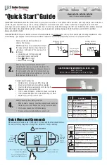
VFC 15-150
Brand: IBC Pages: 84

Ac-U-Temp ACMSS00507
Brand: A.O. Smith Pages: 4

CLASSIC 24
Brand: Ideal Boilers Pages: 8
ALTA-120
Brand: U.S. Boiler Company Pages: 2

NeOvo EcoNox EFU 22
Brand: DeDietrich Pages: 52

IRB-12
Brand: Ikon Pages: 16

KNIGHT WH 55-399
Brand: Lochinvar Pages: 80

Optima 901
Brand: Optima Pages: 8

Solo 110
Brand: Prestige Pages: 104

Excellence
Brand: Prestige Pages: 114

V8H SERIES
Brand: U.S. Boiler Company Pages: 96

K2
Brand: U.S. Boiler Company Pages: 108

Solo 3 PFL 30
Brand: Baxi Pages: 48

Broile System
Brand: Bryan Boilers Pages: 2

BE-210-W4T7
Brand: Bryan Boilers Pages: 4

Eura Condensing
Brand: Hermann Pages: 60

Netaheat Electronic 10/16
Brand: Potterton Pages: 24

WTC-OB 18-B
Brand: Weishaupt Pages: 132


