background image


48 

www.qualitrolcorp.com 

Calibrating the Input Channels 

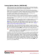
1.  Open the Factory Calibrator tool. 

2.  Select the input channel to calibrate. 

3.  Click [Calibrate]. The 

Input Channel Calibration

 window displays. 

4.  In the terminal block that corresponds to the input module being calibrated, enter the 

signal value displayed in the 

Set input signal to

 field. 

Important:


The 

Set input signal to

 field displays the value of the external signal that 

must be applied to the module terminals. For the RTD Input Modules, the 
input signal is expressed in terms of degrees C. If you continue the calibration 
procedure without inputting the correct excitation (stimulus) signal, you will 
overwrite the calibration with invalid data. This will cause the monitor to 
malfunction. 


5.  After you have entered the input signal on the terminal block and it is stabilized, click 

[Next] to accept the value in the 

Set input signal to

 field. 

Note: 


All channels require at least a two-step calibration procedure. (The Tap Position 
Module requires every position to be calibrated.) The [Next] button changes to 
[Finish] for the second step in the procedure. If you want to return to the previous 
step, click [Back]. 

6.  Enter the value for the second input and click [Finish]. The calibration of this channel is 

complete. 

Содержание 509ITM Series

Страница 1: ...ITROL 509ITM Series www qualitrolcorp com QUALITROL 509ITM 100 QUALITROL 509ITM 200 QUALITROL 509ITM 300 Intelligent Transformer Monitor Hardware and Software Instructions Document ID IST 099 1 ECN 43...

Страница 2: ...ights reserved Information subject to change without notice All trademarks are properties of their respective companies as noted herein IST 099 1 Information in this document is subject to change with...

Страница 3: ...ut Module 509ITM 300 12 Potentiometer Input Module 12 DC Voltage Input Module 12 Current Input Module 12 Dry Contact Closure Module 12 Powered Contact Closure Module 13 Installation 14 Location and Mo...

Страница 4: ...oftware Instructions 39 General Information 39 Connecting to the 509ITM 39 Installing Running the Software 39 Desktop Communications Window 39 File Menu 40 Establishing Communications with the 509ITM...

Страница 5: ...le Calculation Setup Method 69 Advanced Calculation Setup Method 73 Output Relays 78 Relay Tabs 79 Relay Control 79 Seasonal Setpoint 82 Ambient Temperature Forecast 83 Cooling Equipment Exerciser 86...

Страница 6: ...ad Tap Changer Monitor 509ITM 300 119 LTC Requirements and Recommendations for Use 119 LTC Monitor Setup 120 Tap Position 121 Tap Count 122 Tap Motor Sensing 122 Load Current 123 Alarm Setup 123 High...

Страница 7: ...ing and Exporting Configuration Files 138 Expansion Module Option 139 Location and Mounting 140 Input Supply Power 142 Communications 142 Input Modules 143 Calibrating the 509ITM 146 Calibrating Remot...

Страница 8: ...m can monitor up to eight total parameters up to sixteen if an Expansion Module is added such as Liquid Temperatures Main Tank Top or Bottom Load Tap Changer Winding Temperatures Ambient Temperatures...

Страница 9: ...r friendly computer aided setup software that can be supplied with non intrusive easy to retrofit sensors About These Hardware Instructions These Hardware Instructions provide all the information you...

Страница 10: ...int source and value on the DISPLAY the MENU key is used to access the programming menu and the RESET key is used to reset the maximum and minimum values while in the program menu or unlatch any latch...

Страница 11: ...C When ordering the 509ITM from the factory the temperature requirements need to be specified CT Input Module The CT Input Module is used to monitor winding temperatures winding currents motor current...

Страница 12: ...l dial is set to the center of the potentiometer range and the high and low readings are simply ratios of the angular deflections from the normal setting Qualitrol gauges use a 340 angular degree pote...

Страница 13: ...odule is used to monitor a powered contact and it indicates on the display whether it is opened or closed An open means there is no connection between the contacts and closed indicates a shorted conne...

Страница 14: ...rmer panel for installation of the monitor Important Note the mounting differences between the enclosure style and the panel only style Allow space below the monitor for the wiring harness 4 Install t...

Страница 15: ...s TB2 16 is not an earth ground 9 Connect the input power TB1 14 15 and earth ground to TB1 16 Universal power supply 100 240 VAC 50 60 Hz 45 260 VDC CAUTION Installing power outside of the recommende...

Страница 16: ...OM to view change or modify the settings of the 509ITM to meet your requirements Warning Switch off the power supply before performing installation or maintenance Hazardous voltage may still be presen...

Страница 17: ...gned to be flush mounted inside a transformer control cabinet on any smooth surface Four 0 28 in square holes are provided for use with the 0 25 in diameter carriage bolts The monitor requires an appr...

Страница 18: ...18 www qualitrolcorp com Fiberglass Enclosure and Panel Mount 509ITM Steel Enclosure 509ITM 14 50 368 21 56 548 11 06 281 20 00 508 16 00 406 23 06 586 4X 41 10 MOUNTING HOLES 86 22 TYP...

Страница 19: ...the requirements of the National Electrical Code NEC or any international code that is in effect For CSA UL applications a switch or circuit breaker must be installed near the 509ITM where the switch...

Страница 20: ...removable fuse of GMA 250V T3 15A the 5 kV Impulse Unit has no internal fusing if it becomes necessary to replace this fuse The fusing must be replaced with the same type and rating that was original...

Страница 21: ...ow fuse rated at 1 25 or 1 5 A at 600 V CAUTION Do not use DC voltage for powering the heater RTD Input Modules Each RTD Input Module is specifically built to function with only a 10 ohm copper RTD or...

Страница 22: ...e sensed into the CT opening Push the CT sensor back together and check that it is fully engaged As shown in the CT Input Connections figure connect the output wires of the clamp on CT to the terminal...

Страница 23: ...TM 300 For each Tap Position Input Module one Load Tap Changer Resistor Bridge is required The resistor bridge must be made up of equal value resistors from 40 2 2500 ohm each The resistor bridge may...

Страница 24: ...red to measure liquid level flow or gas accumulation The module must be calibrated on site See the Using the Factory Calibrator Tool Advanced users only section in the Software Instructions The three...

Страница 25: ...gnal Either of these options can be a transducer that is 2 wire self powered from the transducer 2 wire powered from the input module 3 wire powered from the input module For each Current Input Module...

Страница 26: ...26 www qualitrolcorp com Current Input Wiring...

Страница 27: ...tial across the switch contact of 0 volts when closed a voltage measurement of 50 V AC DC is also considered closed and a potential greater than 80 volts AC DC contact is open For applications where a...

Страница 28: ...0 A and the sets are accessed on Terminal Block TB1 see the Relay Wiring figure for the Enclosure and Panel Mount monitors Refer to the Software Instructions for configuring the relays controlling sig...

Страница 29: ...efer to Functional Specifications section for maximum load The output signals are accessed on Terminal Block TB2 terminals 1 through 8 See the Remote Output Signal Terminals figure for the Enclosure a...

Страница 30: ...the Black Box fiber optic modem line driver ME540A ST and the Dymec line repeater 5846 F ST See the Optional Fiber Optic Connection figure for the connection to this option The RS 485 connection may...

Страница 31: ...ll and into Viewing Mode The Up and Down Arrows or ENTER will move you individually through each relay that has actuated If the relay has been latched and the parameters that actuated the relay are no...

Страница 32: ...he Down Arrow or ENTER will move you to the Data Logger Option to download the Data Logging data to a memory stick If no key activity takes place for 60 seconds the monitor automatically reverts to Au...

Страница 33: ...or Inactive Press the Up or Down Arrows or ENTER to move through the LTC Monitor values for all active systems If no key activity takes place for 60 seconds the monitor automatically reverts to Auto S...

Страница 34: ...used to enter the Customer Setup in the remote software If you are not authorized to change these settings press MENU to go back to Viewing Mode Scrolling The Up and Down Arrows allow you to change th...

Страница 35: ...he column displays that the cooling monitor is inactive the cooling monitor has either not been installed or the user did not make it active See the Software Instructions for making a cooling bank act...

Страница 36: ...active the operator will view a zero value for the measured current This will not cause the LTC alarm relays to actuate because the Load Tap Changer system only uses the active inrush and steady state...

Страница 37: ...Controls Eight large keys for programmable settings and user interaction Front Panel Membrane UV stabilized polyester Input Parameters Input Modules Up to 8 up to 16 with Expansion Module option Accur...

Страница 38: ...ocols DNP 3 0 Level 1 slave Modbus ASCII IEC 60870 IEC 61850 Memory Data Logger 20 variables able to log 14 variables at 1 minute store rates for over 90 days without overwriting Event Recorder 8 indi...

Страница 39: ...ng to the 509ITM 1 Check that the 509ITM is connected to the main power and is energized 2 Connect a USB cable between the USB port on your PC and the port on the 509 ITM or Connect an RS 232 cable be...

Страница 40: ...ns file Open Opens an existing communications file qco Save Saves the communications data under the current communications file name Save As Saves the communications data with a new communications fil...

Страница 41: ...rt is connected to on your PC Off line You can run the software offline without being connected to the 509ITM 1 With no communications to the 509ITM established click the Off line check box 2 Click on...

Страница 42: ...Setup window displays if any communications parameters have been changed and not saved before clicking Close All A successful communications link is indicated when No error message displays An unsucc...

Страница 43: ...n RETRY Button Click this button to attempt to establish communications with the 509ITM again IGNORE Button Click this button to ignore the communications error However for correct operation of the sy...

Страница 44: ...Setup 111111 The Factory Setup tool can only be entered by Qualitrol factory personnel This section is reserved for the factory except in the Demo mode offline Remember Me Check Box By checking in th...

Страница 45: ...ts on the 509ITM LCD and relay LEDs appear on your PC screen The monitor requests an update from the 509ITM three times every second There are eight control buttons on your PC screen Test Reset Menu E...

Страница 46: ...remotely as you desire The 509ITM responds to the simulated signals as if they were the actual field signals With the exception of the CT Temperature signals the transfer from the field to the simulat...

Страница 47: ...inute timer resets Using the Factory Calibrator Tool Advanced users only The Factory Calibrator tool allows you to calibrate most inputs When you first enter the Calibrator Signal Selection window the...

Страница 48: ...n terms of degrees C If you continue the calibration procedure without inputting the correct excitation stimulus signal you will overwrite the calibration with invalid data This will cause the monitor...

Страница 49: ...use it is done at the factory Saving Calibrations in Files You can save calibration values in files using the File pull down menu These files have the default file extension qca2 Import Allows you to...

Страница 50: ...rations Note You can save configurations as files which you can use to restore settings or to pre configure before connecting to the 509ITM See Importing and Exporting Configuration Files Note All 501...

Страница 51: ...Type Displays whether the monitor is a Transformer Monitor TM Cooling Monitor TCM or Load Tap Changer Monitor LTC System Index Displays the system buttons required to set up and view the parameters o...

Страница 52: ...opens when you click System Settings from the Setup window This window allows you to set the configuration for the items displayed in the different sections of the window More Information Password Set...

Страница 53: ...r and Simulator tools even if they have different passwords This is because all of the passwords can be changed in the User Setup tool so it is treated as the master password When passwords are change...

Страница 54: ...figure the time and date values stored in the 509ITM Note The time and date values can also be changed along with the front panel operations Current PC Time Displays the current time of the PC that is...

Страница 55: ...55 www qualitrolcorp com 3 Continue with the setup procedure...

Страница 56: ...on is in California set the Time Zone Difference to 3 hours Current PC date Displays the current date of the PC that is connected to the 509ITM when the Time and Date Setup window is opened 509 Time a...

Страница 57: ...option is installed the following fields are available for setup Heater Function Allows you to enable or disable this feature Heater Setpoint Allows you to set the temperature at which the Heater is...

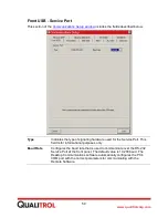
Страница 58: ...ns when you click Communications from the Setup window This window allows you to configure the 509 ITM communications ports displayed in the different tabs of the window More Information Front USB Ser...

Страница 59: ...dware used for the Service Port This field is for informational purposes only Baud Rate Configures the baud rate that is used to communicate over the RS 232 Service Port at the front panel The default...

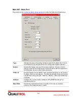
Страница 60: ...a 2 wire duplex remember to add jumpers to terminal block TB2 as explained in the Hardware section under Communications Protocol Selects between the available communications protocols to be used by t...

Страница 61: ...f parity for the Main Port communications protocol The default is none Number of Stop Bits Selects the desired number of stop bits for the Main Port communications protocol The default value is 1 Aux...

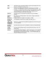
Страница 62: ...Hot Spot Module DGA sensor or Expansion Module communications Baud Rate The Baud Rate for all digital communications is 9600 Number of Data Bits The Data Bits for digital communications should be set...

Страница 63: ...particular 509ITM unit Copper Fiber If an Ethernet FX option board is installed then selecting Fiber will make it the active port If there is no option board or if communicating through the RJ45 conn...

Страница 64: ...64 www qualitrolcorp com Load Button Loads all communications parameters from the PC into the 509ITM All new communications parameters take effect only after the 509ITM hardware has been reset...

Страница 65: ...he types of available modules are described in the Modules section of the Hardware Instructions To begin click the tab of the input module that you want to configure The Input Module Setup window disp...

Страница 66: ...ctory according to the input module that was ordered and installed If the module type indicates undefined there is no physical module installed in that location Input Module Function Enables and disab...

Страница 67: ...is the scaled minimum value for the corresponding minimum input value High End Value field is the scaled maximum value for the corresponding maximum input value Custom Units Label If the Use Custom S...

Страница 68: ...eater than the current it will be sensing This will prevent saturation the sensor value is as close to the maximum current reading as possible This will optimize the resolution CT ratio 2 fields Provi...

Страница 69: ...Method Advanced Calculation Setup Method Simple Calculation Setup Method This method allows you to configure the simple scaling parameters for input module types that are set to CT Temperature The wi...

Страница 70: ...70 www qualitrolcorp com More Information Input Module Number and Input Signal Name Fields Winding Rise Parameters Oil Rise Parameters...

Страница 71: ...Adder Allows you to select one of the available RTD Input Modules The selected RTD Input Module will be the liquid temperature measurement that is added to the winding curve simulation for example top...

Страница 72: ...e fields in this section are described below Oil rise temperature Allows you to set the temperature rise value of the transformer oil at nominal load This is derived from the Transformer Heat Run Repo...

Страница 73: ...response than the Simple Calculation Method But to use this method the winding rise parameters are required for each cooling stage The formulas for calculating winding temperatures for this window wer...

Страница 74: ...ynamically alter the parameters to match the present cooling stage being used You can individually program each winding for accurate representation of the winding rise gradient You can also program th...

Страница 75: ...its secondary side which is the winding to be configured In ONAN mode 30 MVA 32 kV 5 2000 X In first cooling mode 40 MVA 32 kV 5 2000 X In second cooling mode 50 MVA 32 kV 5 2000 X Note For a three p...

Страница 76: ...rise for a specific load increase The winding temperature reaches its final value for a given load in approximately five time constants Note You can program the 509ITM for up to four cooling modes inc...

Страница 77: ...a given current input Note It takes approximately five time constants to elapse for the temperature to reach full value for a given load If the oil time constant is not provided the IEC 354 Loading G...

Страница 78: ...lay 1 tab being selected By selecting the different tabs you can index through the relay array To begin click the tab of the output relay that you want to configure The Output Relay Setup window displ...

Страница 79: ...power supply malfunction if in the failsafe mode Note Relays that are not in Test Lock Out mode are also actuated when the system relay is actuated Relay Control This section of the Output Relay Setup...

Страница 80: ...tor Energized Set Point Loss of Power to Monitor Non failsafe NC C NC C NO C NC C Failsafe NC C NO C NC C NC C Test lock out On Off When you press the TEST switch on the display panel of the 509ITM th...

Страница 81: ...of the control signals in the Control Signal Matrix table have sensor errors the relay actuates Off If a control signal has an error it is not used in controlling the relay The status of the other co...

Страница 82: ...s are met the Seasonal Setpoint has priority over the setpoint in the Control Signal 1 column Seasonal function Allows you to enable or disable this feature Configure Button Opens the Seasonal Setpoin...

Страница 83: ...nt is active 2 Click Load Ambient Temperature Forecast This section of the Output Relay Setup window includes the fields described below Ambient temperature forecast installed A check mark indicates t...

Страница 84: ...summer while the ambient temperature forecast is used for a specific condition for example a heat wave If the ambient temperature exceeds the number of the Threshold Value for more than the number of...

Страница 85: ...mbient temperature probe installed as one of its input modules this feature cannot be used Measurement Period Select the number of hours to measure the ambient temperature Exceeded Hours Select the nu...

Страница 86: ...t Relay Setup window includes the fields described below Important Do not enable the exerciser for any relay that controls a trip function Enabled Disabled Allows you to enable or disable this feature...

Страница 87: ...rolcorp com Low temperature setpoint If a Low temperature module is entered then the cooling equipment exerciser will not actuate the relay as long as the measured temperature is below the low tempera...

Страница 88: ...en it equals or exceeds the setpoint value meets the conditions to actuate the relay in that column Hysteresis 4 fields Allows you to select a switching differential required to de actuate the relay W...

Страница 89: ...ckout feature This has now been incorporated into the relay matrix and can be accomplished using the following example 1 Set Control Signal 1 to WINDING Setpoint to 80 00 C and Actuation Direction to...

Страница 90: ...ease of 100 PPM This same feature can be used for a falling control signal if the actuation direction is set to down Rate of change time period The Rate of change time period is the rolling time perio...

Страница 91: ...to provide information to Supervisory Control Data Acquisition SCADA systems or remote indications You can configure each output to send data from any of the inputs or send a derived calculation such...

Страница 92: ...range for the current loop output Example An RTD measures temperatures from 40 120 C You select an output of 4 20 mA and a custom range of 0 100 For temperature measurements of 40 0 C the current loop...

Страница 93: ...Bank Switching Setup window opens when you click Bank Switching from the Setup window This window configures the cooling circuit management feature This feature provides a method for evenly spreading...

Страница 94: ...y 4 and Relay 4 selects Relay 6 you must set up Relay 6 to select Relay 2 The bank switching is accomplished by exchanging all the matrix controls of the selected relay with the one selecting it This...

Страница 95: ...ow The TransLifeTM feature provides detailed information for up to three winding temperatures of the transformer To begin click the TransLifeTM tab that you want to configure The TransLifeTM Setup win...

Страница 96: ...ber of the RTD Input Module that will measure the ambient temperature Note This field is only required if you are using the Critical Forecast feature It is not required for the Consumed Life or Temper...

Страница 97: ...ields described below Life Consumption Formula Variables Depending on the application allows you to select different Unity Hot Spot Temperatures by entering the corresponding constants Unity Hot Spot...

Страница 98: ...e assumed transformer life Operating Hours Displays the operating hours of the 509ITM You can preset this number Critical Forecast This section of the TranslifeTM Setup window allows you to set up the...

Страница 99: ...nt load conditions Time to Critical Temperature 3 Range fields Displays the time calculated for the winding temperature to reach the critical setpoint values given the present loading oil winding temp...

Страница 100: ...ree rise in temperature The Temperature Profiler section includes the fields described below Unity Temperature Allows you to enter a temperature value where one hour of operating time equals one hour...

Страница 101: ...101 www qualitrolcorp com...

Страница 102: ...lick Data Logger from the Setup window The Data Logger can store the data of up to 20 signals These signals can be any of the following types input module measurements relay status fiber optic tempera...

Страница 103: ...store rate you can maximize the number of measurements while minimizing the amount of data logging memory space The sample rate is used in conjunction with the sample type to 1 Take the maximum minimu...

Страница 104: ...will download all valid data logging memory to the flash drive inserted in the side USB A port on the 509ITM in a csv file format If no flash drive is installed the data will not download Erase Memor...

Страница 105: ...ve cleared an event the event recorder automatically provides a time stamp and stores the specific event In addition if you select the System Snapshot all enabled input values and relay statuses are a...

Страница 106: ...sociated with event The maximum name size is 24 alpha numeric characters Record Type This section of the Event Recorder Setup window includes the fields described below Time and date stamp only Allows...

Страница 107: ...ding to the control signal which when it equals or exceeds the setpoint value meets the conditions to trigger the event Hysteresis 4 fields Allows you to select a switching differential required to cl...

Страница 108: ...em NOTE Once the memory is cleared it can not be recovered Close Selecting Close will exit this menu tab Cooling System Monitor 509ITM 200 The Cooling Monitor Setup Selection window opens when you cli...

Страница 109: ...109 www qualitrolcorp com All of these functions allow you to maximize the use of the cooling function and help extend transformer life...

Страница 110: ...k Setup The Cooling Bank Setup window opens when you click Setup from the Cooling Monitor Selection window The Cooling Bank Setup window includes all of the parameter settings needed to operate the co...

Страница 111: ...e Cooling Bank Setup window includes the fields described below Bank monitor Indicates which cooling bank is to be configured This field is for informational purposes only Bank actuating relay Allows...

Страница 112: ...ted here to be a matrix controlled relay the relay will no longer operate as a cooling system alarm relay Cooling bank Allows you to enable or disable the Cooling Monitor Note If you disable all the c...

Страница 113: ...the learning mode This field is for informational purposes only Minimum current value Displays one of the following items the minimum steady state current achieved during normal operation since the v...

Страница 114: ...in the learning mode This field is for informational purposes only Minimum peak value Displays one of the following items the minimum peak current over time achieved during normal operation since the...

Страница 115: ...arm Yes No Enables Yes Disables No the alarm relay actuation if the number of actuations exceeds the setpoint threshold limits Run Time This section of the Cooling Bank Setup window includes the field...

Страница 116: ...llows you to enter a temperature value to actuate the alarm relay if the differential calculation equals or exceeds the value Hysteresis Allows you to select a switching differential of the temperatur...

Страница 117: ...samples the working transformer cooling system using the actual input sensors and displays the measured parameters These values can then help you select the appropriate settings in the Cooling Bank S...

Страница 118: ...is being evaluated Qualitrol recommends a minimum of 10 cycles to get a good system average 6 Click Initialize The cooling system begins to cycle The relay controlling the fan pump motor de energizes...

Страница 119: ...the life of the load tap system More Information LTC Monitor Requirements and Recommendations for Use LTC Monitor Setup LTC Requirements and Recommendations for Use The installation of the Load Tap C...

Страница 120: ...More Information Load Tap Changer Monitor 509ITM 300 LTC Monitor Setup LTC Monitor Setup The LTC Monitor Setup window opens when you click Load Tap Changer from the Setup window This window allows yo...

Страница 121: ...udes the fields described below Load tap changer monitor Allows you to enable or disable the Load Tap Changer Monitor Tap position module Allows you to select the installed position of the input modul...

Страница 122: ...udes the fields described below Motor current input module Allows you to select an installed position of the input module which measures the motor current of the tap position changer Switch contact mo...

Страница 123: ...of two alarms is to allow for the prioritization of events that might occur with the LTC Monitor Example If multiple taps occur or if the motor current exceeds the setpoints the installation might re...

Страница 124: ...tor Setup window This window allows you to set the configuration for the items displayed in the different sections More Information Alarm Relay Setup Total Tap Counts Multiple Tap Movements Tap Run Ti...

Страница 125: ...y that you selected here as a matrix controlled relay the relay will no longer operate as a load tap changer alarm relay Do not select the same relay for both the high priority alarm and low priority...

Страница 126: ...nd minutes of the actuation of the alarm relay after the control signal has continually exceeded the setpoint threshold Total Tap Counts This section of the High Priority LTC Alarm Setup window includ...

Страница 127: ...n of the alarm relay if the value in the Tap run time setpoint field is exceeded Tap Counts Per Period This section of the High Priority LTC Alarm Setup window includes the fields described below Tap...

Страница 128: ...steady state current equals or falls below the value Actuate alarm Yes No Enables Yes Disables No the actuation of the alarm relay if the motor current exceeds the setpoint threshold limits Starting...

Страница 129: ...can reset or preset the count by entering a new number Actuate alarm Yes No Enables Yes Disables No the actuation of the alarm relay if the number of motor actuation counts exceeds the setpoint value...

Страница 130: ...rence in temperature reaches 10 C but will de actuate at 7 C 10 3 7 Actuate alarm Yes No Enables Yes Disables No the actuation of the alarm relay when the differential temperature measurement exceeds...

Страница 131: ...ee windows Cooling Bank Setup High Priority LTC Alarm Setup Low Priority LTC Alarm Setup The 509ITM can manage up to four difference calculations For each calculation select two inputs to measure the...

Страница 132: ...en you are finished with your selections click Load The difference pair will be assigned to the selected difference calculation View LTC Values The View LTC Values window opens when you click View LTC...

Страница 133: ...ement decisions You have the option of resetting to zero or preloading this value as required Average break current Displays the average break current Knowing how heavily or lightly loaded the taps ha...

Страница 134: ...lues are normal for those conditions or if there is a reason for alarm On the other hand the calculated winding temperature uses formulas IEEE and IEC models to calculate the winding temperature based...

Страница 135: ...feedthroughs that are installed in the tank wall plate to the optical hot spot module These cables come in varying lengths from 5 15 meters Custom lengths are available Optical Hot Spot Module The opt...

Страница 136: ...methods of determining a winding temperature can you make full use of the data as a predictor for possible transformer problems You can accomplish this by using the matrix control of the output relays...

Страница 137: ...Calculated Value exceeds 10 degrees or the Direct Measurement minus the Calculate Value falls below 5 degrees Important Because of the variance in the temperature throughout the windings depends on th...

Страница 138: ...own menu These files have the default file extension qca The pull down menu commands are described below Import Allows you to import a configuration from a file stored on your PC Export Allows you to...

Страница 139: ...ops etc The Expansion Module communicates to the 509ITM unit through a digital cable wiring and has the same input power supply range as the 509ITM unit NOTE When first applying power to the 509ITM an...

Страница 140: ...18 INPUT MODULE 14 TB19 INPUT MODULE 15 TB17 INPUT MODULE 13 INPUT MODULE 12 TB14 TB15 INPUT MODULE 11 INPUT MODULE 10 TB13 INPUT MODULE 9 4 2 TB 22 TB21 TB21 INPUT POWER UNIVE RSAL 90 264 VAC 47 63 H...

Страница 141: ...3 TB16 TB20 INPUT MODULE 16 TB18 INPUT MODULE 14 TB19 INPUT MODULE 15 TB17 INPUT MODULE 13 INPUT MODULE 12 TB14 TB15 INPUT MODULE 11 INPUT MODULE 10 TB13 INPUT MODULE 9 4 2 TB 22 TB21 TB21 INPUT POWE...

Страница 142: ...modules is done through the auxiliary RS485 communications port on the back of the 509ITM unit TB2 14 15 16 The protocol for the 509ITM to communicate with the expansion module and hot spot modules is...

Страница 143: ...143 www qualitrolcorp com Input Modules To set up the input modules installed on the expansion module click on Input Expansion Modules in the Customer Setup window...

Страница 144: ...144 www qualitrolcorp com The following window will appear...

Страница 145: ...ent loops data logging event recording and communication protocols can be configured to use all active installed input modules be they from the main 509ITM unit or residing on the expansion module The...

Страница 146: ...PUT MODULE 16 TB18 INPUT MODULE 14 TB19 INPUT MODULE 15 TB17 INPUT MODULE 13 INPUT MODULE 12 TB14 TB15 INPUT MODULE 11 INPUT MODULE 10 TB13 INPUT MODULE 9 4 2 TB 22 TB21 TB21 INPUT POWER UNIVERSAL 90...

Страница 147: ...mountings are provided for retrofit 1 5 NPT 2 5 NPT and 4 inch bolt circle flange versions are available When mounted in place of a Qualitrol Rapid Pressure Rise Relay the hydrogen monitor includes a...

Страница 148: ...un a four wire shielded twisted pair cable from the 509ITM to the DGA Hydrogen Sensor and run the connections as follows COMMUNICATIONS WIRING 509ITM DGA SENSOR TB2 14 T RXD B TB1 7 9 T RXD B TB2 15 T...

Страница 149: ...149 www qualitrolcorp com In the Customer Setup window screen if a DGA sensor is installed it will display the DGA button which will allow the user access to the DGA setup screens...

Страница 150: ...s min The minimum hydrogen value read for the present calendar day in PPM Today s max The maximum hydrogen value read for the present calendar day in PPM Min X days ago The minimum hydrogen readings f...

Страница 151: ...n values measured over the last twelve days giving a quick visual representation of the hydrogen levels in the transformer Sensor Information Clicking on Sensor Information will display the DGA sensor...

Страница 152: ...splays the serial number of the product Sensor board serial number Displays the serial number of the sensor printed circuit board Manufacturing date Displays the manufacturing date of the sensor Senso...

Страница 153: ...aboratory to another may vary as much as 15 Therefore Qualitrol also recommends using the same laboratory each time a sample is collected By correlating the DGA sensor to that particular laboratory th...

Страница 154: ...sults from the laboratory enter the hydrogen reading as measured by the laboratory into the Lab Correlation section in the H2 lab correlation value Then enter the date and click on Load Correlation Th...

Страница 155: ...n The next step is to decide what to do with those measurements Interpretation of the measurement values is dependent on a number of variables which are specific to the installation being measured the...

Страница 156: ...s of more than 10 per month above typical concentration values is generally considered a prerequisite for pronouncing the fault as active Much higher rates of gas increase such as 50 per week and or e...

Страница 157: ...s 0 5 mA 0 10 mA 0 20 mA This procedure provides steps for recalibrating the current loop outputs You will need the following items to perform this procedure 509ITM ammeter or multi meter set to measu...

Страница 158: ...libration values incorrectly might cause the 509ITM to malfunction 4 Connect the ammeter or multi meter set to measure DC milliamps to TB2 pins 1 and 2 with the positive probe on 1 5 In the Calibrator...

Страница 159: ...which is the value used to calibrate for a 4 20 mA current loop output 7 Adjust the slide bar control until the ammeter displays the correct lower calibration value for the new current loop output ra...

Страница 160: ...ue for the new current loop output range Current Loop Output Range Upper Calibration Value 4 20 mA 20 00 mA 0 5 mA 5 00 mA 0 10 mA 10 00 mA 0 20 mA 20 00 mA 10 Click Finish 11 Repeat the process for t...

Страница 161: ...the 509ITM to malfunction Calibrate only the Potentiometer input module When you are finished immediately exit the Calibration tool Before You Begin 1 Connect the potentiometer output wires of the Lev...

Страница 162: ...k the radio button for the input module that displays Potentiometer In the example above this is Input 3 CAUTION Check again that you have selected the correct input module before proceeding Calibrati...

Страница 163: ...alibration window displays The Set input signal to field prompts you to set the pointer to minimum MIN 6 Adjust the case face until the pointer is set at the minimum position Case face adjusted with t...

Страница 164: ...Next The Input Channel Calibration window now prompts you to set the pointer to maximum MAX 8 Adjust the case face until the pointer is set at the maximum position Case face adjusted with the pointer...

Страница 165: ...the steps for calibrating a Tap Position Resistor Bridge to a 509ITM CAUTION Except for the Potentiometer Level Gauge and Tap Position Input Modules the input modules of the 509ITM are calibrated usi...

Страница 166: ...Procedure 1 Connect the computer to the 509ITM and start the Remote Software The Desktop Menu window displays 2 Click Connect and enter the password for the Customer Setup tool 509 for newer models 1...

Страница 167: ...167 www qualitrolcorp com The Customer Setup window displays 4 Click Load Tap Changer...

Страница 168: ...module field select the LTC Resistor input module 6 In the Total number of taps field enter the correct tap position number 7 Click Load 8 Exit from the Configurator Customer tool 9 Enter the passwor...

Страница 169: ...k the radio button for the input module that displays LTC Resistor In the example above this is Input 4 CAUTION Check again that you have selected the correct input module before proceeding Calibratin...

Страница 170: ...istor values require that you calibrate every position of the Tap Position Resistor Bridge starting with the lowest tap position For this reason the transformer should be offline during the calibratio...

Страница 171: ...he tap position up one tap and click Next Repeat for the entire range of taps Important Be sure to increment the tap position only once for each increment of the Input Channel Calibration window 17 Af...

Страница 172: ...f the page with the corresponding calibration values in parentheses These values should range from 0 00 1 00 in approximately equal increments 4 If the calibration values are not correct check the wir...

Страница 173: ...necessary to view the Device Manager in Windows to determine the communications port which has been assigned when you connect to the ITM After you plug a USB A to B cable into your PC and the front p...

Страница 174: ...dary voltage 2 Divide by the instrumentation CT ratio that is being used to give you the load current for that delta T rise Example The transformer is a 14000 kVA with a winding of 34400 V The instrum...

Страница 175: ...r When the controlling input signal reaches the setpoint the relay changes states so that the common normally open side is shorted closed and the common normally closed side is open A non failsafe rel...

Страница 176: ...hs as short as possible and use the heaviest gauge wire that s practical for the application Wire has resistance and shorter lengths and thicker wire minimizes that resistance Dress the wires so that...

Страница 177: ...ut updating the 509ITM unit in the field purchasing a new module and getting an update software disk 2 The calibration for the RTD Input Module has been altered or overwritten If the 509ITM was incorr...

Страница 178: ...178 www qualitrolcorp com Appendix...

Страница 179: ......

Страница 180: ......

Страница 181: ......

Страница 182: ...CHAN 3 91 4 C WIND 2 CHAN 3 CURRNT 1210 1 A WIND 3 CHAN 4 90 1 C WIND 3 CHAN 4 CURRNT 1188 7 A AMBIENT CHAN 5 21 3 C CONS TK CHAN 6 72 1 C LTC TNK CHAN 7 69 0 C C down enter down enter down enter down...

Страница 183: ...M 200 MODEL RUSH 25 8 AS MIN1 1841 072501 RUN UPPER SETPT CM1 25 0 A down enter down enter up up LTC MONITOR INACTIVE LTC MONITOR ACTIVE MAX TAP COUNT 03 TAP 3469 MAX RUN TIME 02 TAP 22098 H PRES TAP...

Страница 184: ...ACTUATION COUNTS RELAY 4 00567 OPERATING HOURS TOTAL 011221 H down enter down enter down enter down enter down enter up up up up up down enter down enter down enter down enter up up down enter down e...

Страница 185: ...43 2 AS RUSH LOWER SETPT HI ALM 25 4 AS down enter down enter down enter down enter down enter up up up up up RUN UPPER SETPT HI ALM 21 0 A down enter up RUN LOWER SETPT HI ALM 15 0 A down enter MTR...

Страница 186: ...R SETPT LO ALM 15 0 A down enter MTR ACTUATION SP LO ALM 3000 down enter TOP OIL LTC OIL LO SP 0010 0 C down enter up up up down enter I top of column J WINDING CHAN 8 ON enter RS232 BAUD RATE 19200 R...

Страница 187: ...ps 71 custom scaling 52 D data logger 80 date configuration 46 DC voltage input module 5 input wiring 15 difference calculation 108 digital communications 20 display configuration 47 dry contact closu...

Страница 188: ...put module 4 input wiring 12 running software 29 S save calibrations 41 seasonal setpoint 64 service port 49 setup system 44 simple calculation setup 54 simulator application 38 software instructions...

Страница 189: ...s substation and transformer monitoring and protection devices used by electric utilities and manufacturing companies It is the global leader in sales and installations of transformer asset protection...

Отзывы: