


104
JUN 2020
USER GUIDE
6
OPERATOR MAINTENANCE
DS-200iQ / DS-600iQ
REV 00
5. Lift the roller assembly feed shaft upwards to remove it from the feed bed.
6.
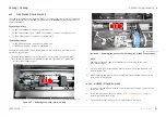
Slip off the roller tyres as shown in Figure 6.44, and replace them as required.
QTL-RND-OPS-00000026-A-00
Figure 6.44 – Replacing the feed tyres
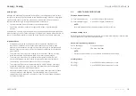
7. When replacing the feed shaft roller assemblies back into the feed bed,
ensure that the ‘flat spot’ on the shaft is located on the operator side as
shown in Figure 6.45.
QTL-RND-OPS-00000271-A-00
Figure 6.45 –
Shaft ‘flat spot’ located on the operator side
This indicates a one-way clutch freewheel direction, and if installed
on the wrong side, the shaft will rotate but the wheels will not drive.
8. Ensure the drive dogs on each end are fully engaged as shown in Figure 6.46.
QTL-RND-OPS-00000027-A-00
Figure 6.46 – Drive dog fully engaged
9. Once complete, re-secure the feed bed plate to the chassis and the three
thumb screw knobs.
Содержание DS-200iQ
Страница 1: ...USER GUIDE DS 200iQ DS 600iQ...
Страница 7: ...1 USER GUIDE DS 200iQ DS 600iQ 1 SAFETY STANDARDS COMPLIANCE...
Страница 11: ...5 USER GUIDE DS 200iQ DS 600iQ 2 INTRODUCTION...
Страница 16: ...10 USER GUIDE DS 200iQ DS 600iQ 3 INTEGRATED MAIL OPERATING SYSTEM IMOS...
Страница 41: ...35 USER GUIDE DS 200iQ DS 600iQ 4 OPERATOR IMOS SETTINGS...
Страница 62: ...56 USER GUIDE DS 200iQ DS 600iQ 5 OPERATOR INSTRUCTIONS...
Страница 92: ...86 USER GUIDE DS 200iQ DS 600iQ 6 OPERATOR MAINTENANCE...
Страница 114: ...108 USER GUIDE DS 200iQ DS 600iQ 7 TROUBLESHOOTING GUIDE...
Страница 117: ...111 USER GUIDE DS 200iQ DS 600iQ 8 TECHNICAL SPECIFICATIONS...
Страница 129: ...123 USER GUIDE DS 200iQ DS 600iQ 9 DISPOSAL INSTRUCTIONS...