background image

Chapter 3 Robot Debugging  and Components Maintenance


Document Version    V1.1.0 (03-07-2022) 

                                                        22


Step 4 

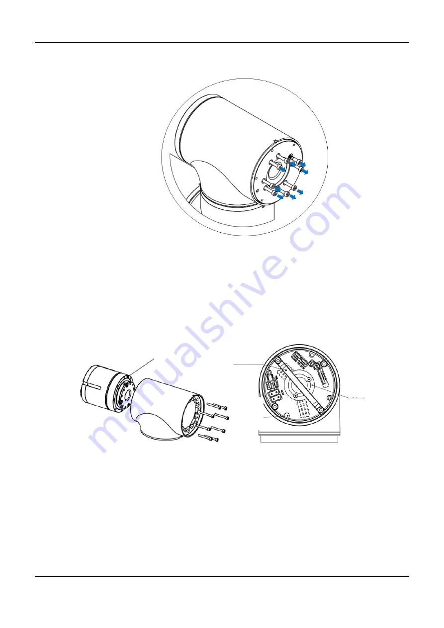
Use Allen wrench to remove the fastening screws from the flange of the Axis J6 

module and remove the Axis J6 flange, as shown in Figure 3-12. 


Figure 3-12 Remove the screws from the Axis J6 module 

Step 5 

Gently push and remove the old module from the end flange. Remove the wear 

ring, module rubber plug and cable holder from the module. 

Step 6 

Install the wear ring, module rubber plug and cable holder on the new module, 

as shown in Figure 3-13. Apply a layer of Black Power Sealant on the outer 

ring of the module (the area between the screw holes), then install the module 

on the shell, and tighten the screws (apply a layer of thread glue when 

installing the screws) with a screw torque of 2.4N·m, as shown in the figure.   


Figure 3-13 Axis J6 module installation diagram 

Step 7 

Re-thread the signal and power cables at the end pass-through interface to 

Axis J3 and connect the interface. 

Step 8 

Connect the communication and power cables on the Axis J6 module one after 

another, fix the cables of Axes J3 ~ J6 with cable ties, and then re-install the 

waterproof cover at the rear end. 

Step 9 

  Fill the four countersunk head screws in the inner ring of the module with 

Black Power Sealant. Apply a layer of Black Power Sealant on the inner ring of 

the flange (the area between screw holes), and then restore the flange end, 

Module outer ring 

Cable holder 

Wear ring 

Module 
rubber 
plug 

Содержание MS6MT

Страница 1: ......

Страница 2: ...Maintenance Manual MS6MT Robot MS6MT 0900 3546 Document version V1 1 0 Issued on March 07 2022 QKM Technology Dongguan Co Ltd...

Страница 3: ...r This manual applies to Electrical Engineer Maintenance Engineer Mechanical Engineer Technical Support Engineer Signs meanings The signs in this document clearly indicate any dangers warnings attenti...

Страница 4: ...logy Co Ltd and QKM possesses the ownership of the trademark Disclaimer QKM does not assume any direct indirect special incidental or consequential loss or liability due to improper use of this manual...

Страница 5: ...rsion history contains the accumulated information on each update of the document and the latest version of the document includes the updates in all previous versions of the document Version Time Chan...

Страница 6: ...ng operation 3 1 2 4 Precautions when a fault occurs 3 1 2 5 Precautions during maintenance 4 1 2 6 Precautions for safe shutdown 5 1 3 Waste disposal 5 Chapter 2 Routine Maintenance and Exception Han...

Страница 7: ...t of Axis J5 module 23 3 3 3 Replacement of Axis J4 module 25 3 3 4 Replacement of Axis J3 module 28 3 3 5 Replacement of Axis J2 module 31 3 3 6 Replacement of Axis J1 module 34 3 4 Replacement and m...

Страница 8: ...3 11 Remove the fastening screws from end flange 21 Figure 3 12 Remove the screws from the Axis J6 module 22 Figure 3 13 Axis J6 module installation diagram 22 Figure 3 14 Axis J6 flange inner ring 2...

Страница 9: ...l 32 Figure 3 31 Remove the Axis J2 flange 33 Figure 3 32 Remove the fastening screws from the Axis J2 module 33 Figure 3 33 Axis J2 module installation diagram 34 Figure 3 34 Axis J2 flange inner rin...

Страница 10: ...List of Figures Document Version V1 1 0 03 07 2022 VIII List of tables Table 2 1 Handling of common exceptions 8...

Страница 11: ...ices related to industrial robots Do not use the robot illegally QKM will not be liable for any losses due to illegal use by users Common situations involving illegal use beyond specified operating ra...

Страница 12: ...the power is on electric shock or equipment failure may be caused Connect the cables properly Do not place heavy objects on the cables or forcibly pull or clamp the cables Failure to do so may result...

Страница 13: ...1 2 3 Precautions during operation Before putting the robot into operation for the first time be sure to inspect it to ensure that the equipment and its devices are complete with perfect functions fo...

Страница 14: ...ated parts prevent foreign matter from adhering to or entering the robot The parts screws etc removed shall be correctly installed in their original positions In case of redundant or insufficient part...

Страница 15: ...pplies related to the equipment and ensure that the equipment restores to the safe state for restart Set up protective devices to indicate the current state of the equipment and prevent others from in...

Страница 16: ...perform routine inspection and maintenance of the equipment find faults and resolve them in a timely manner 2 1 Maintenance cycle 2 1 1 Regular check To keep the robot in good working condition preve...

Страница 17: ...body are loose and whether the wires and cables are twisted or tangled Encoder battery Check whether the battery voltage is lower than 3 15V Robot surface Check whether there is dust on it Work space...

Страница 18: ...ow speed 2 2 Handling of common exceptions Exceptions may occur during the operation of MS6MT Robot The common exceptions are analyzed and handled as follows Table 2 1 Handling of common exceptions Co...

Страница 19: ...Change the IP of the PC connected to the robot to be in the same network segment as the robot s IP and then connect it Multiple problems in PC network card Disable all other network cards in the PC e...

Страница 20: ...each axis rotates at an angle of less than 360 then perform a rough calibration of the robot zero to prevent internal cables from damage due to excessive winding Confirmation of rotation angle of each...

Страница 21: ...tion Preparation for operation Laptop network cable calibration block Software ARM software The operation steps are as follows Step 1 Connect the robot to the power supply then connect the laptop for...

Страница 22: ...er aligning the grooves use the calibration block to perform auxiliary positioning to enable them to be completely inserted Use the calibration block provided in the accessory box for rough calibratio...

Страница 23: ...er the execution is completed the encoder values of each axis will be displayed in the output window and each value will be recorded Step 5 Open My Computer enter FTP 192 168 10 120 in the input box c...

Страница 24: ...es in the configuration file Note The coordinates of the origin of Axes J1 J2 and J4 are special and 131072 needs to be added after the encoder values as shown in Figure 3 4 Figure 3 4 Replacement of...

Страница 25: ...e connector The distribution of end pass through cables of the robot is shown in Figure 3 5 Figure 3 5 Distribution of end pass through cables When removing the axis Axis J6 modules from the upper par...

Страница 26: ...ables so hard to avoid damage to them When a robot module fails determine the position of the module Pull out the cables from Axis J3 to the rear end of the determined axis module Remove the waterproo...

Страница 27: ...t the lower part Step 2 Disconnect the pass through signal connector from the power connector at the end of Axis J3 Step 3 Use scissors to cut off the cable ties fixing cables on the modules of Axes J...

Страница 28: ...ntenance of module interface cables The MS6MT Robot module comprises communication interfaces power supply interfaces and an encoder battery interface The distribution of the interfaces on the module...

Страница 29: ...nput interface of the module The power output interfaces of Axes J1 and J2 are not equipped with connectors so pay attention to it during removal and installation The Axis J6 module is a terminal modu...

Страница 30: ...face of the module as shown in Figure 3 10 Figure 3 10 Ground wire connection diagram of Axes J2 J4 Removal Step 1 Use Allen wrench to loosen the ground terminal fastening screws Step 2 Disconnect the...

Страница 31: ...is detected in the Axis J6 module remove and replace the Axis J6 module following the steps below Tools Allen wrench one set anti static gloves scissors cable ties Step 1 Remove the end pass through c...

Страница 32: ...crew holes then install the module on the shell and tighten the screws apply a layer of thread glue when installing the screws with a screw torque of 2 4N m as shown in the figure Figure 3 13 Axis J6...

Страница 33: ...rface with reference to Section 3 2 3 Step 3 Use a small flathead screwdriver or similar tool to gently remove the black flexible flat ring from the junction of Axes J5 and J6 and pull it back from it...

Страница 34: ...3 17 Figure 3 17 Remove the screws from the Axis J5 module When removing the fastening screws from the Axis J5 module hold the Axis J5 module with hand to prevent the module from falling at the end o...

Страница 35: ...rproof cover at the rear end Step 11 Fill the four countersunk head screws in the inner ring of the module with Black Power Sealant Apply a layer of Black Power Sealant on the inner ring of the flange...

Страница 36: ...de the black ring back as shown in Figure 3 20 10 screws are visible with 5 screws on each side of the joint Use a special open end wrench to loosen the screws by at least two and a half turns for eac...

Страница 37: ...7 Gently push and remove the old module from the fixed end Remove the wear ring module rubber plug and cable holder from the module Step 8 Install the wear ring module rubber plug and cable holder on...

Страница 38: ...rews in the inner ring of the module with Black Power Sealant Apply a layer of Black Power Sealant on the inner ring of the flange the area between screw holes and then restore the flange end and tigh...

Страница 39: ...3 25 Figure 3 25 Unscrew the waterproof end cover Step 2 Disconnect the communication cable power cable and encoder battery cable from the rear interface panel of the Axis J3 module Step 3 Disconnect...

Страница 40: ...ntly push and remove the old module from the fixed end as shown in Figure 3 27 Figure 3 27 Remove the screws from the Axis J3 module Step 6 As shown in Figure 3 28 apply a layer of Black Power Sealant...

Страница 41: ...le Step 8 Connect the communication and power cables one after another Reconnect the end pass through signal and power cables and restore the waterproof covers at both ends 3 3 5 Replacement of Axis J...

Страница 42: ...lack ring back 10 screws are visible with 5 screws on each side of the joint Use an open end wrench to loosen the screws by at least two and a half turns for each Then pull the two parts apart and gen...

Страница 43: ...en wrench to remove the fastening screws from the Axis J2 module Figure 3 32 Remove the fastening screws from the Axis J2 module Step 5 Gently push and remove the old module from the fixed end Step 6...

Страница 44: ...countersunk head screws in the inner ring of the module with Black Power Sealant Apply a layer of Black Power Sealant on the inner ring of the flange the area between the screw holes and then restore...

Страница 45: ...end of Axis J1 clockwise and disconnect the communication cable power cable and encoder battery cable from the interface panel of the Axis J1 module Step 3 Place the robot on the cushion and use Alle...

Страница 46: ...nd remove the old module from the fixed end Step 9 Apply a layer of Black Power Sealant on the outer ring of the new module the area between the screw holes then install the module on the Axis J1 shel...

Страница 47: ...9 Base flange inner ring Step 13 Fix the base plate with a screw torque of 0 8N m 3 4 Replacement and maintenance of encoder battery Fix the encoder battery on the sheet metal at the rear end of each...

Страница 48: ...to be replaced and connect the new encoder battery to the corresponding backup interface Step 4 Disconnect the old encoder interface and remove the old encoder battery Step 5 Fix the new encoder batte...

Страница 49: ...ing signs around the robot to prevent other workers from incorrectly operating it Remove and replace the robot components only after the robot is powered off The 48V relay module is provided separatel...

Страница 50: ...rews according to the structural characteristics of the equipment In case of any problems in the discharge resistor replace it in time by following the steps below Tools Allen wrench one set straight...

Страница 51: ...to your inquiry in detail If your robot or equipment fails during use you can contact our service department and provide information below as much as possible Model and serial number of robot or equi...

Страница 52: ...ces Document Version V1 1 0 03 07 2022 42 Scan QR Code to follow QKM Province Tel 86 0769 27231381 Fax 86 0769 27231381 8053 Postcode 523808 E mail service qkmtech com Website www qkmtech com Scan WeC...

Отзывы: