


Chapter 3 Robot Debugging and Components Maintenance
Document Version V1.1.0 (03-07-2022)
26
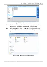
following the steps below:
Tools: Allen wrench (one set), anti-static gloves, special tool for removing pins, scissors,
cable ties.
Step 1
Remove the end pass-through cables with reference to Section 3.2.1.
Step 2
Remove the power and signal cables from the Axis J4 module interface with
reference to Section 3.2.3.
Step 3
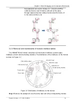
Use a small flathead screwdriver or similar tool to gently remove the black
flexible flat ring from the junction of Axes J4 and J5 and pull it back from its
original position on the joint shell. Then slide the black ring back, as shown in
Figure 3-20. 10 screws are visible, with 5 screws on each side of the joint. Use
a special open-end wrench to loosen the screws by at least two and a half
turns for each. Then pull the two parts apart and gently rotate by 10°
counterclockwise until they are mechanically stopped (with keyhole type holes).
After that, the Axis J4 can be completely separated from the Axis J5.
Figure 3-20 Remove the screws from the Axes J4 and J5 shell
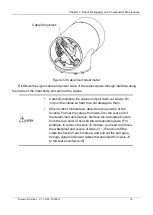
After removing the mounting screws and pins from Axis J4, hold the
Axis J5/J6 with hand to prevent the module from falling.
Step 4
Remove the Axis J5/J6 and slowly pull out the cables from the middle of the
Axis J4 module.
Step 5
Use Allen wrench to remove the fastening screws from the Axis J4 flange and
remove the flange, as shown in Figure 3-21.
Содержание MS6MT
Страница 1: ......


