background image

6. CONTROLLER PROGRAMMING

5.1. OPERATION MODE SELECTION

Opera RL controller can operate in one of the following modes:
1. NORMAL - basic operation mode,
2. PRESET - the "manual field" mode - the saving and rendering of the previously saved scenes, 

chasers and sequences is off,

3. C/F - memory card communication mode - settings storage,
4. PC - computer communication mode - software updating, settings storage and edition.

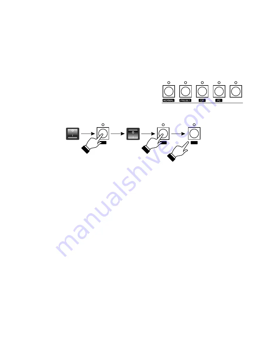
The  operation  mode  selection  is  being  made  during 
controller switching on. To select an operation mode:
1. Switch the controller off.
2. Press and hold one of the keys shown - appropriate for 

the selected mode.

3. While holding the key switch the controller on.
4. After 3 seconds approximately release the key.

ATTENTION:

The  NORMAL  and  PRESET  modes  settings  are  saved  in  the  controller's  memory  and  the 
controller will be automatically switched to one of this modes after turning on.
The C/F and PC modes are not saved. For that reason after turning the controller off and on again, 
Opera RL will be automatically switched to the operation mode it run according to before the C/F 
or PC modes were selected.

Switching to the selected mode is confirmed by:
- for the NORMAL mode - the software number is displayed,
- for the PRESET mode - the PRESET LED is lit,
- for the C/F mode - the "C" and "F" letters are displayed on the banks' displays,
- for the PC mode - the GO LED is lit.

4

6.1. SCENES CREATION AND EDITION

~3 secs

1.  In  the  PROGRAMMING  block  press  the  SCENE  key  -  the  LED  above  will  light  up,  what 

confirms the scenes programming has begun.

2. Select a number for the programmed scene. To do so, with the PAGE MEMORY "+" or "-" key 

select a range, where you want this scene to be placed and, with one of the MEMORY keys, 
choose the precise number for this scene. The digit, visible on the PAGE MEMORY display, 
represents the successive ten of scenes. If you want to, for instance, select 75 as the number of 
your scene, with the "+" or "-" keys set 7, and then press the 5 key. Above this key the LED will 
light up, and the number of the selected scene will be shown on the SCENE/CHASER display.

Содержание PX125 Opera RedLine

Страница 1: ...INSTRUCTION MANUAL PX125 Opera RedLine R...

Страница 2: ...dition 7 Scenes and chasers rendering 8 Sequences rendering 9 PRESET operation mode 10 Monitor 11 FLASH card saving and reading 12 PC communication 13 Connections couplings 14 Technical specification...

Страница 3: ...places with temperature lower than 2 C or higher than 40 C 11 Cleaning with damp duster only PX125 has to be cut off the power supply directly PX125 Opera Redline is a professional console for theatr...

Страница 4: ...00 channels are divided into 10 banks 10 channels each The digit visible on the display represents the successive ten channels The digit displayed under the key represents the channel number within on...

Страница 5: ...oftware is permanently improved you can find the latest software version on the producer s website If its number is greater than displayed we recommend you to update your software The update process d...

Страница 6: ...t reason after turning the controller off and on again Opera RL will be automatically switched to the operation mode it run according to before the C F or PC modes were selected Switching to the selec...

Страница 7: ...edition To do so when no LEDs are lit above the CHANNEL keys press the SELECT ON OFF key and adjust the brightness for all channels paying attention to range selection where needed 7 After all the adj...

Страница 8: ...r of currently edited step on the STEPdisplay 6 You can copy the selected scene when needed 1 Press the SCENE key in the PROGRAMMING block 2 In the MEMORY block press a key corresponding with the scen...

Страница 9: ...LED represents the channel selected in a different range 4 Adjust the brightness of the selected channels with the sliders The sliders affect the brightness of channels in the currently selected range...

Страница 10: ...DE slider adjust the step to step fading smoothness On the X FADE display the 0 value stands for the instant change 99 for an entirely smooth change With the SPEED slider adjust the steps duration tim...

Страница 11: ...EXT keys set the number of step on the STEP display you want to be last one in the sequence Press the END and then the ENTER key in the PROGRAMMING block 7 You can insert a new step between the existi...

Страница 12: ...of the rendered scenes or chasers To render a previously defined scene the LED above the SCENE CHASER key must light green When this LED lights red press the SCENE CHASER key Move the slider in the ME...

Страница 13: ...n launch one scene or chaser only dimming all the rest of currently rendered light configurations Press the SOLO key the LED above will light up and move the slider corresponding with the required sce...

Страница 14: ...the X FADE slider or FREEZE B for the speed slider The scene that is currently launched under the frozen slider can be lit up and dimmed as many times as you want to until the freeze feature is turne...

Страница 15: ...e scenes settings are realized with the set of A field sliders upper sliders set and B field sliders lower set of sliders The channels brightness can be set with the appropriate sliders you can also c...

Страница 16: ...oller operation mode slider MASTER circuit 101 sliders SPEED and X FADE 14 A colour monitor can be connected to the Opera RedLine controller where all the informations about controller s current opera...

Страница 17: ...sed The controller and card co operation mode is indicated by the letters and on the left displays banks The SCENE CHASER LED indicates the card activity the red colour stands for the action the green...

Страница 18: ...card occure we do not guarantee the file system integrity The saved set is useless at least partly and the memory card can contain the lost clusters In such situation the best solution is to check an...

Страница 19: ...nputs audio 0 dB RS 232 outputs DMX 512 RS 232 monitor power supply power consumption weight dimensions width heigth depth 17 13 CONNECTION COUPLINGS ground audio signal not connected JACK stereo 2 5...

Страница 20: ...ent ground installation Name of producer Address of producer declares that the product Name of product Type answers the following product specifications LVD EMC Additional informations Krak w 01 06 20...

Отзывы: