background image

23 

Copyright © Puretec Pty Ltd 2020

SOL-TA Commercial Series User Guide

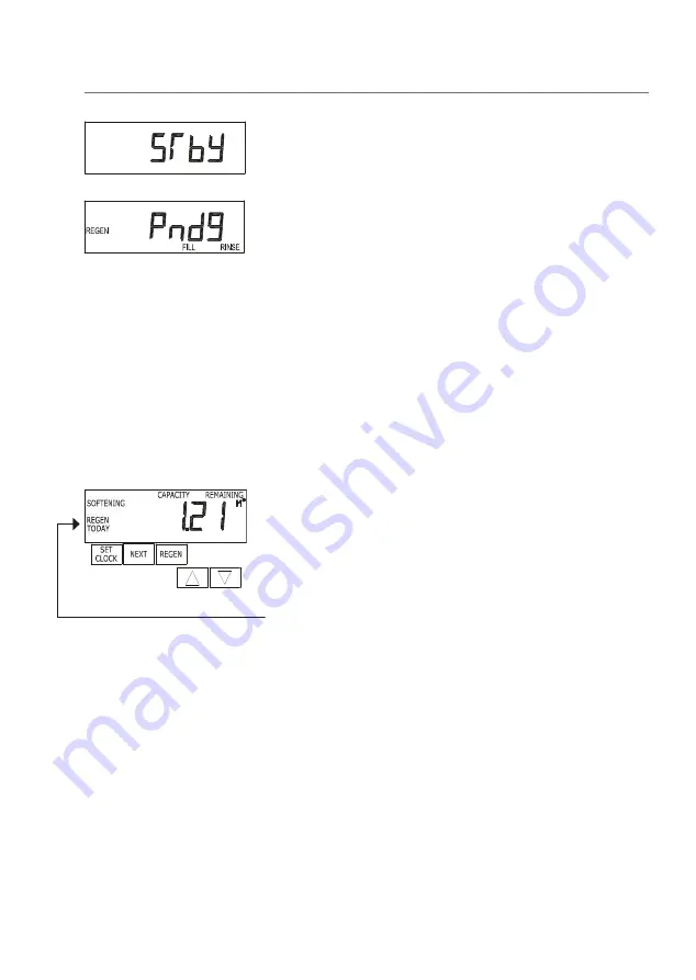
STby:

 Is displayed in alternator systems when a valve is in 

standby state. 

REGEN Pndg RINSE FILL:

 Is displayed whenever a zero-capacity 

tank has transferred to an off-line stateand is currently waiting 
to initiate the second portion of a regeneration cycle. Viewed only 
when Delayed Rinse and Fill is set to ON. 

Sometimes there is a need to regenerate the system sooner 
than when the system calls for it, usually referred to as manual 
regeneration. There may be a period of heavy water usage 
because of guests or a heavy laundry day for example. 

Immediate Regeneration: 

To initiate a manual regeneration 

immediately, press and hold the "REGEN" button for three seconds. 
The system will begin to regenerate immediately. 

Note: 

The control valve may be forced through the various 

regeneration cycles by pressing the "REGEN" button. 

Delayed Regeneration: 

To initiate a manual regeneration at the 

preset delayed regeneration time, press and release "REGEN". The 

words "REGEN TODAY" will flash on the display to indicate that the 

system will regenerate at the preset delayed regeneration time. 

If you pressed the "REGEN" button in error, pressing the button 
again will cancel the request. 

If the regeneration time option is set to "on 0" there is no set 

delayed regeneration time so "REGEN TODAY" will not activate if 

"REGEN" button is pressed. 

Note:

 For softeners, if brine tank does not contain salt, fill with 

salt and wait at least two hours before regenerating. 

Step 2CS

Step 3CS

Step 4CS

Step 2CS

Step 3CS

Step 4CS

Manual Regeneration

Manual Regeneration

Содержание SOL-TA Series

Страница 1: ...olumetric Water Softening System SOL TA Commercial Series For correct operation installation it is essential to observe these instructions AUG2020 WMTS103 2016 Licence No WM 74593 Australian Certification Services ...

Страница 2: ...iagram 8 Parts Identification 9 Installation Procedure 10 Programming 15 Advanced Programming optional 16 DP Switch Programming optional 20 General Operation 22 Manual Regeneration 23 Start Up 24 Regeneration 24 Replenishment of Salt Supply 25 Type of Salt Used 25 Brine Tank Clean Out 25 Media Replacement 25 Bypass Valve Operation optional accessory 26 Troubleshooting Guide 27 Warranty 31 ...

Страница 3: ...od of non use more than 2 weeks Note For point of entry installations an approved dual check backflow prevention device must be installed When line pressure exceeds 500 kPa a pressure limiting valve must be installed Note Water softener salt not supplied Installation Note A water filter system tap like any product has a limited life and may eventually fail Also sometimes failure happens early due ...

Страница 4: ...en Frequency ________ Days Water Analysis Information Hardness ___________ ppm mg L Iron ___________ ppm mg L Manganese ___________ ppm mg L pH ___________ TDS Total Dissolved Salts ___________ ppm mg L Conductivity ___________ EC uS cm Chloride ___________ ppm mg L Sodium ___________ ppm mg L Installation Record For future reference fill in the following data Installation Record ...

Страница 5: ...able amounts of soluble iron if consideration is given when selecting model and regeneration settings For best results contact Puretec to discuss Install Water Conditioning Equipment Correctly Select the location of your water softener with care Various conditions which contribute to proper location are as follows Install as close as possible to a drain Install in correct relationship to other wat...

Страница 6: ...s Chlorine free chlorine tolerance is 0 5ppm high chlorine levels permanently damage the softening resin is not covered under warranty If chlorine exceeds this limit we recommend a carbon pre filter such as the WH2 or CFS Series Please refer to Puretec for a specific recommendation In any case a carbon pre filter is recommended to protect against chlorine spikes prolong the resin life Things to Re...

Страница 7: ...ure Min Max 138 862 kPa Operating Temperature Min Max 0 40 C protect from freezing Electrical Connection 240V 50 Hz Inlet outlet Connection 1 BSPT Drain Connection Overflow Connection SOL45 TA SOL60 TA Width mm W 608 mm 710 mm Height mm H 1762 mm 1711 mm Maximum Salt Storage Capacity 75 kg 75 kg W 370 900 H 430 900 ...

Страница 8: ...8 Installation Operation Manual Copyright Puretec Pty Ltd 2020 Exploded Diagram Exploded Diagram 2 1 3 4 11 12 10 13 14 15 16 17 9 2 1 3 4 5 6 7 Secondary Tank Primary Tank 8 ...

Страница 9: ... 5 WTD3030 Pressure Tank UV Sheild x 2 6 Interconnect Pipe Kit 7 WTV4250 TA Volumetric Valve 8 WTB5070 Plastic Fitting Kit Elbow 9 Drain Tube Assembly Item Part no Description 10 WTV5135 Transformer Suit Auto Valve 11 WTV5110 Valve Cover 12 WTV5000 Bypass Assembly purchased separately 13 KTV6SVC Black Tubing 14 KEC66 Elbow Connector 15 WTB4000 Brine Pickup Assembly 16 WTB2200 Brine Tank 17 WTB5150...

Страница 10: ...________ ppm mg L Conductivity ___________ EC uS cm Chloride ___________ ppm mg L Sodium ___________ ppm mg L 130 0 3 0 1 7 275 404 121 96 Customer Service Helpline 1300 140 140 AU 0800 130 140 NZ Extra Items Required 2 Unpack the Equipment Ensure all parts are present and have not been damaged in trasport You should have 1 User Guide Volum etric Water Softening System SOL TA Commercial Series For...

Страница 11: ...ver the top end of the riser pipe in the primary pressure tank labelled Vessel 1 making sure no media can enter the tube 3 Ensure that the riser pipe is sitting in the cradle at the base of the tank Then using a wide mouth funnel place the media in the tank as per the numbering on the buckets Buckets are labelled Vessel 1 Pour 1 2 3 etc Put Pour No 1 in first followed by 2 etc as required 4 Remove...

Страница 12: ...urning the knob counterclockwise Connect the bypass assembly followed by the plastic fittings Hand tighten the knobs do not overtighten 6 7 Connecting the Pressure Tanks Install the Interconnect Fittings between the secondary tank head and the control valve Side of the valve where the yellow Connect to second tank sticker is located tighten up by hand only Top View ...

Страница 13: ...nsure the drain line is not kinked The line must not travel more than 2 4m up and no more than 6 m long from the valve otherwise increase the diameter of the drain line Connect drain and overflow to sewer or stormwater whatever is approved by local authority for salty discharge water Ensure drain line has an adequate air gap of 2 times the pipe diameter or 25 mm whichever is larger Brine Installat...

Страница 14: ...ed accordingly to local codes 6 2 Proceed to Programming section 12 Connecting the Overflow 11 Connect tubing onto the 5 8 overflow fitting tubing not supplied and run the line to the drain Do not connect the overflow into the drain line as it must be a direct and separate line to the drain Allow an air gap as per the drain line Make sure the drain is not higher than the overflow Overflow Brine ...

Страница 15: ...ould be performed followed by a manual regeneration if convenient Installer Display Settings Note If optional Advanced Programming or optional DP Switch Programming is required complete those steps prior to programming the Installer Display Settings 1 To enter the installer display settings press NEXT and simultaneously for about 5 seconds and release Note Press REGEN at any time to return to the ...

Страница 16: ...MAL on 0 were selected in Set Regeneration Time Option in Advanced Settings Press NEXT to go to step 6 6 Preset to skip this this step Note Next Regeneration Time minutes can be set in this step using or This option is only available when NORMAL or NORMAL on 0 were selected in Set Regeneration Time Option in Advanced Settings 1 Press NEXT and simultaneously for about 5 seconds and release 2 Choose...

Страница 17: ...0S Step 11S Step 12S Step 13S Step 14S Step 15S EXIT OEM SOFTENER SYSTEM SETUP EX SCREENS Step 6CS Step 7CS Step 2S Step 3S Step 4S Step 5S Step 6S Step 7S Step 8S Step 10S Step 11S Step 12S Step 13S Step 14S Step 15S EXIT OEM SOFTENER SYSTEM SETUP EX SCREENS Step 6CS Step 7CS Step 2S Step 3S Step 4S Step 5S Step 6S Step 7S Step 8S Step 10S Step 11S Step 12S Step 13S Step 14S Step 15S EXIT OEM SOF...

Страница 18: ...ing or If value is set to AUTO Capacity will be automatically calculated and reverse capacity will be automatically estimated Off Regeneration will be triggered soley by the day override setting see Installer Display Settings step 4 Volume Regeneration will be by the value specified in M3 If oFF or volume is used the hardness display will not be allowed to be set in Installer Display Settings step...

Страница 19: ...hile in service and then deactivates after a set period of time or after the meter stops registering flow whichever comes first Set Litres Softening Regen On Relay activates after a set number of litres have been used while in service or during a regeneration and then deactivates after a set period of time or after the meter stops registering flow whichever comes first ERROR Relay closes whenever ...

Страница 20: ...nges from 1 second to 200 minutes If L on or L softening regen on is selected in step 14 the relay will deactivate after the time set has expired or after the meter stops registering flow whichever comes first Ranges from 1 second to 20 minutes Press NEXT to exit Advanced Programming 1 Press NEXT and simultaneously for 5 seconds and release Then press NEXT and simultaneously for 5 seconds and rele...

Страница 21: ...tely dPdEL If the switch is closed for an accumalative time of 2 minutes a regeneration will occur at the scheduled delayed regeneration time Once the dP switch is triggered the PC board will display REGEN TODAY and switch tanks immediately At the delayed regeneration time the triggered unit will then regenerate Note If the dP function dPon0 or dPdEL is set the delayed rinse and fill feature is no...

Страница 22: ...e in cubic metres since last reset User 4 Shows current time Regeneration and Error Screens Regen Screen Displays the time remaining in the current cycle Pressing REGEN advances to the next cycle Pndg Screen In alternator systems when the unit is waiting to initiate the first cycle step of regeneration REGEN Pndg is displayed EXIT TO DISPLAY SCREENS Step 6CS Step 7CS Step 2S Step 3S Step 4S Step 5...

Страница 23: ... the REGEN button for three seconds The system will begin to regenerate immediately Note The control valve may be forced through the various regeneration cycles by pressing the REGEN button Delayed Regeneration To initiate a manual regeneration at the preset delayed regeneration time press and release REGEN The words REGEN TODAY will flash on the display to indicate that the system will regenerate...

Страница 24: ...st tap downstream of the filter system after the filter system 4 Allow water to flow through the system slowly and allow all air to escape out of the closest tap Wait until the water is flowing out of the tap and then increase the flow slowly up to full flow Allow to run for 5 10 minutes 5 Close the opened tap and check for leaks 6 Conduct a full manual regeneration 7 Your system is ready for use ...

Страница 25: ...s required when topping up the salt level Type of Salt to Use Any type of water softener salt may be used but for best results we recommend using coarse solar salt called water softener salt or alternatively pool salt Brine Tank Clean Out To help prevent service problems the brine tank should be emptied and flushed out with a garden hose when dirt and other insolubles accumulate Clean out with a w...

Страница 26: ...ER EXITS SUPPLY WATER ENTERS NO WATER EXITS SUPPLY WATER IS SHUT OFF FROM THE HOUSE THE VALVE TREATED WATER EXITS SUPPLY WATER ENTERS SUPPLY WATER EXITS SUPPLY WATER ENTERS OF F OF F OF F OF F Normal Operation Bypass Operation Diagnostic Mode Shut Off Mode Bypass Valve Operation optional accessory ...

Страница 27: ...ration set incorrectly C Reset regeneration time Time of day flashes on and off A Power outage s A Reset time of day replace battery CR2032 and then perform a dry reset Valve does not regenerate when performing a manual regeneration A No power to valve A Refer to No display blank screen on valve B Broken drive gear or drive cap assembly B Replace drive gear or drive cap assembly C Broken piston ro...

Страница 28: ...l of regenerant E Refill regenerant tank F Valve fails to draw regenerant F Refer to Valve fails to draw in regenerant G Insufficient regenerant level in regenerant tank G Contact Puretec for assistance H Leak from seal spacer stack assembly H Clean replace spacer stack assembly Control valve uses too much regenerant A Incorrect refill setting A Contact Puretec for assistance B Incorrect program s...

Страница 29: ... cap assembly E Tighten replace drive cap assembly Error Code 1001 Control unable to sense motor movement A Motor not inserted fully into engage position motor wires broken or disconnected A Disconnect power make sure the motor is fully engaged check for broken wires make sure two pin connector is connected to the two pin connection on the PC Board labelled MOTOR Connect power and perform a dry re...

Страница 30: ...regeneration A Check motor connections Perform a dry reset B Foreign material lodged in valve B Clean replace piston spacer stack assembly Perform a dry reset C Drive bracket not correctly installed C Snap drive bracket in correctly Perform a dry reset Error Code 1004 Control valve motor ran too long and timed out trying to reach home position A Drive bracket not correctly installed A Snap drive b...

Страница 31: ...tion and service work should be completed by qualified tradespeople Faulty operation due to unqualified persons will result in voided warranty coverage Chlorine free chlorine tolerance is 0 5ppm high chlorine levels permanently damage the softening resin is not covered under warranty Warranty Australia This warranty is given by Puretec Pty Ltd ABN 44 164 806 688 37 43 Brodie Road Lonsdale SA 5160 ...

Страница 32: ......

Отзывы: