background image

3. X-axis & Extruder assembly

Original Prusa MINI+ kit assembly

49

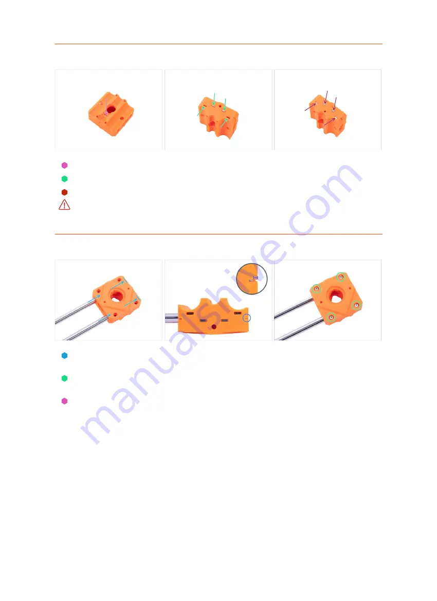
STEP 3

 Assembling the Z-carriage

Insert the M3nS nut in the MINI-Z-carriage-front part.
Insert four M3nS nuts in the top side of the MINI-Z-carriage-front.
Turn the part upside down and insert four M3nS nuts in the bottom holes.

Always 

make sure that all M3nS nuts are inserted all the way down 

into the holes.

Use the 2.0mm Allen key to push the nuts fully inside.

STEP 4

 Assembling the Z-carriage

Carefully slide both smooth rods all the way into the MINI-Z-carriage-front. 

Before

inserting the smooth rods, check if there are no obstructions inside the holes.

Look sideways on the MINI-Z-carriage-front through the inspection hole and 

check

that the smooth rod is fully inserted into the plastic part.

Secure all parts together with four M3x12 screws.

Содержание Original Prusa MINI

Страница 1: ...on 18 Step 9 Installing the heatbed spacers 18 Step 10 Y axis front parts preparation 19 Step 11 Comparison of extrusions 19 Step 12 Mounting the Y plate front 20 Step 13 Mounting the MINI Y plate front 20 Step 14 Y belt idler parts preparation 21 Step 15 Preparing MINI Y belt idler 21 Step 16 Preparing MINI Y belt idler 22 Step 17 Mounting the MINI Y belt idler 22 Step 18 Y axis smooth rods parts...

Страница 2: ...er parts preparation 44 Step 60 Securing the MINI Z top assembly 44 Step 61 YZ axis assembly reward yourself 45 Step 62 YZ axis is finished 45 3 X axis Extruder assembly 47 Step 1 Tools necessary for this chapter 48 Step 2 Z carriage parts preparation 48 Step 3 Assembling the Z carriage 48 Step 4 Assembling the Z carriage 49 Step 5 X end parts preparation 49 Step 6 X end parts preparation lubricat...

Страница 3: ...Print head Heatbed assembly 73 Step 1 Tools necessary for this chapter 74 Step 2 Hotend Print fan parts preparation 74 Step 3 Mounting the hotend 74 Step 4 Mounting the print fan 75 Step 5 Hotend fan parts preparation 75 Step 6 Assembling the hotend fan 76 Step 7 Minda holder parts preparation 76 Step 8 Assembling the Minda holder 77 Step 9 Mounting the MINI minda holder 77 Step 10 SuperPINDA sens...

Страница 4: ... 96 Step 19 Connecting the electronics 96 Step 20 Covering the electronics parts preparation 97 Step 21 Covering the electronics 97 Step 22 Gluing the silver label 98 Step 23 Electronics reward yourself 98 Step 24 LCD assembly Electronics are finished 99 6 Spool holder assembly 100 Step 1 Tools necessary for this chapter 101 Step 2 Spool holder parts preparation 101 Step 3 Spool holder parts prepa...

Страница 5: ...Original Prusa MINI kit assembly 5 1 Introduction ...

Страница 6: ...XIS box Please prepare it now Allen keys including one TORX key Needle nose pliers 1x Universal wrench 1x No soldering is required No wire crimping is required STEP 2 Universal wrench description The universal wrench is designed for tightening all these fasteners used on the MINI printer 1 Brass nut 2 M3nN nyloc nut 3 Brass nut 4 Nozzle 5 Heatbed spacer ...

Страница 7: ...rs there are instructions for lubricating the bearings before using them For these instructions the kit includes Prusa lubricant applicator 1x Prusa lubricant 1x STEP 4 Labels guide All the boxes and bags including parts for the build are labelled Each bag or box label describes in which chapter you will need it ...

Страница 8: ...t common screws nuts and PTFE tubes You can also use the enclosed letter which contains Prusa Cheatsheet on the other side You can help prusa3d com cheatsheet from our site Print it at 100 don t rescale it otherwise it won t work STEP 6 Spare bag Every type of fastener is included in a separate special bag If you lose a screw during assembly use one from this bag ...

Страница 9: ...ion for clarity Just hover your cursor over the image and click the Magnifier button View original in the top left corner STEP 8 We are here for you Lost in the instructions missing screw or cracked printed part Let us know You can contact us using following channels Using comments under each step Using our 24 7 live chat at shop prusa3d com Writing an email to info prusa3d com ...

Страница 10: ...de the ESD bag right until you are asked to install them Always touch the sides of the board while manipulating with it Avoid touching the chips capacitors and other parts of the electronics Before you touch the electronics use any conductive steel structure nearby to neutralize any electro static energy Be extra cautious in rooms with carpets which are a source of electrostatic energy Clothes mad...

Страница 11: ... place as soon as you insert the screw in you can remove the tape Using glue isn t recommended as it can partly reach into the thread and you won t be able to tighten the screw properly Whenever you need to fit the nut that doesn t fit properly we recommend using screw pulling technique You will be reminded with Joe s avatar Parts in the pictures are used as an example STEP 11 Pro tip inserting th...

Страница 12: ...pters some even ate them all before they started After completing each chapter or challenging section of the chapter you will be prompted to replenish energy for the following steps Don t eat all the bears before you start or at once Not following instructions will have serious consequences we are currently assembling Prusa Haribo tactical squad for this matter Hide the Haribo for now From our exp...

Страница 13: ...ctions are as brief as they can be Read them Read the comments from the other users They are a great source of ideas We read them too and based on your feedback improve the manual and the entire assembly Use a reasonable force The printed parts are tough but not unbreakable If it doesn t fit check your approach twice Eat the gummy bears as instructed Disobedience won t be tolerated D Most importan...

Страница 14: ...14 Original Prusa MINI kit assembly 2 YZ axis assembly ...

Страница 15: ...Allen key Needle nose pliers Universal wrench STEP 2 Y carriage parts preparation All the printed parts and fasteners needed for this chapter are included in the box YZ X axis For the following steps please prepare Y carriage 1x M3nN nyloc nut 6x M3x10r screw 6x Bearing clip 3x Linear bearing LM8UU 3x included in the Rods package The list continues in the next step ...

Страница 16: ...nting on the printer Follow these instructions carefully STEP 4 Lubricating the bearing Use any piece of fabric as a pad to protect your working surface from grease Make sure the bearing is clean inside Wipe the preservative oil off the bearing surface with a paper towel It is necessary to lubricate all 4 rows of balls inside the bearing Open the lubricant and pierce the hole in the tube with the ...

Страница 17: ...se or too little Take a closer look at the last picture Wipe off excess grease on the outside of the bearing with a paper towel Use this procedure for all three bearings Do not remove the applicator from the tube Keep it prepared for the next chapter The bearings may leave excess grease on the smooth rods after their installation Wipe off any residue with a paper towel STEP 6 Correct bearing orien...

Страница 18: ... bearing Insert two M3x10r screws into the holes in the bearing clip Using your fingers hold the heads of both screws and turn the Y carriage Place the nyloc nuts on both screws Tighten both nuts by using the 2 mm Allen key and the universal wrench Repeat these steps for the remaining two linear bearings STEP 8 Heatbed spacers parts preparation For the following steps please prepare Heatbed spacer...

Страница 19: ...h the universal wrench and 2 5mm Allen key Use this procedure for all 9 heatbed spacers Place the MINI Y belt holder on the bottom side of the Y carriage Orient the holder so that the side with the teeth faces the side with one bearing Double check the MINI Y belt holder orientation Secure it with two M3x12 screws STEP 10 Y axis front parts preparation For the following steps please prepare MINI Y...

Страница 20: ...e Y plate front Place the short extrusion to the left inner side of the MINI Y plate front See the protrusion on the plastic part Do not place the extrusion directly on the protrusion on the left There must be a gap See the picture Slide the extrusion onto the plastic part so that the protrusion fits in the extrusion Secure both parts with two M5x20r screws When tightening the M5x20r screws push o...

Страница 21: ...protrusion on the plastic part Slide the extrusion onto the plastic part so that the protrusion fits in the extrusion Secure both parts with two M5x20r screws When tightening the M5x20r screws push on the extrusion from above STEP 14 Y belt idler parts preparation For the following steps please prepare MINI Y idler 1x Pulley 623 2Z 1x M3nN nyloc nut 1x M3nS nut 2x M3x20 screw 3x ...

Страница 22: ... into the hexagonal hole on the side Push the nut as far down as possible Always make sure that all M3nS nuts are inserted all the way down into the holes STEP 16 Preparing MINI Y belt idler Insert the pulley in the MINI Y belt idler The orientation of the pulley doesn t matter Secure the bearing with the M3x20 screw Don t fully tighten the screw Place your finger on the bearing and ensure it can ...

Страница 23: ... MINI Y belt idler with two M3x20 screws Do not tighten the screws at this time Leave a small gap between the MINI Y belt idler and the MINI Y plate front STEP 18 Y axis smooth rods parts preparation For the following steps please prepare Smooth rods 2x There are two sizes of the smooth rods Prepare two rods with the smaller diameter 8 mm now Smooth rods with a larger diameter 10 mm will be used l...

Страница 24: ...earings The bearings may leave excess grease on the smooth rods after their installation Wipe off any residue with a paper towel STEP 20 Mounting the Y carriage Place the Y carriage on the extrusions The side with one bearing must face to the left Gently slide the smooth rods into the holes in the MINI Y front plate Start with the left rod then the right one Insert two M3nE into the side groove of...

Страница 25: ... picture See the direction of the arrows Place the pulley T16 2GT on the Y motor shaft as shown in the picture Don t press the pulley against the motor Leave a two millimeter gap between both parts Use the universal wrench to set the gap One of the screws must be facing directly against the pad flat part on the shaft Slightly tighten the first screw Turn the shaft and slightly tighten the second s...

Страница 26: ...tor with three M3x12 screws STEP 24 Mounting the MINI Y rear plate Once again make sure that all three M3nE nuts are placed in the extrusion Place the MINI Y rear plate on the smooth rods Push the MINI Y rear plate all the way onto both extrusions Secure both parts with two M5x20r screws When tightening the M5x20r screws push on the extrusion from above To prevent damage to the Y axis motor cable ...

Страница 27: ...s installation Gently push four pads out of the block Keep the other two pads for later Peel the protective film from all four pads Rotate the Y axis so that the Y carriage is facing down and glue four pads on the extrusions like in the picture Pay careful attention to the correct orientation It is recommended to place the Y carriage on a piece of fabric Heatbed spacers can scratch your workbench ...

Страница 28: ...sert one end of the belt into the lower groove of the MINI Y belt holder Make sure the belt teeth are facing up Guide the belt around the MINI Y belt idler pulley Guide the belt around the Y axis motor pulley Insert the second end of the belt into the upper groove of the MINI Y belt holder Secure both ends of the belts by squeezing them into the groove with the 1 5mm Allen key ...

Страница 29: ...g the belt BUT don t try to overstretch the belt as you might damage the printer You can change the tension in the belt by adjusting the two screws on the MINI Y plate front Tighten the screw bring the MINI Y belt idler closer and thus increase the overall tension Release the screw parts will move apart the overall tension will decrease Use the technique described below to test if the belt is prop...

Страница 30: ...el of noise might attract nearby predators Each row of the bears is intended for a specific chapter or is split into specific parts of the chapter The number of the bears is sorted according to the difficulty of the chapter But don t worry Spread the bears in the six rows according to the picture Start from the top If you are missing some bears do not hesitate and immediately visit the nearest can...

Страница 31: ...bottom 1x M3n nut 4x M3nS nut 8x Anti vibration foam pad 1x The remaining foam pad is a spare STEP 33 Assembling the MINI Z bottom Look inside the MINI Z bottom locate two holes and insert two M3nS nuts Use the 1 5mm Allen key to push the nuts fully inside Insert one M3nS nut into the hole on the side Insert one M3nS nut from the front side of the part Always make sure that all M3nS nuts are inser...

Страница 32: ...ress too much on the bottom of the plastic part it may crack Glue the anti vibration pad in the recess shape of the pad STEP 35 Buddy board parts preparation For the following steps please prepare WARNING Make sure to protect the electronics against electrostatic discharge ESD Always unpack the electronics right before you need them Buddy board 1x Keep the silver label for later Note that the anti...

Страница 33: ...ors are properly seated in the holes Secure the board with four M3x8 screws Do not tighten too much You can crack the Buddy board You can insert the screws with the needle nose pliers But be careful avoid scratching the printed circuit board or bend the capacitors You can fatally damage the Buddy board STEP 37 LCD cable parts preparation For the following steps please prepare LCD cable 1x The cabl...

Страница 34: ... board Mind the orientation of the connector there is a notch on one side see the orange circle STEP 39 LCD cable guidance WARNING From now on proceed carefully while moving the XZ axis The LCD cable is facing down and might get damaged In order to protect the cable please follow the instructions below Also don t try any other orientation because it will complicate the assembly Wrap the LCD cable ...

Страница 35: ...tion For the following steps please prepare Extrusion 289 mm 1x Z plate bottom 1x M5x20r screw 2x M3x12 screw 2x M3x20 screw 3x M3x40 screw 1x STEP 41 Assembling the Z axis Place the Z plate bottom part on the front of the extrusion like in the picture Secure it with two M5x20r screws ...

Страница 36: ...ure and slightly tilt the extrusion Move the inclined extrusion to the edge of the plastic part see the yellow circle Straighten the extrusion to 90 STEP 43 Assembling the Z axis Make sure there is no large gap between the Z plate bottom and the plastic part Secure the Z plate bottom with two M3x20 screws Insert one M3x12 screw in the Z plate and tighten it Insert the M3x40 screw into the hole in ...

Страница 37: ... points exactly at the hole in the M3nE nut in the extrusion Join both parts together DON T tighten the screw fully yet STEP 45 Joining the Y and Z axis together Take the second M3nE nut from the left and move it all the way to the right use the Allen key and gently push it in There is a notch inside which will align it properly for the second screw Use the M3x20 screw and again tighten it just sl...

Страница 38: ...g the M3x12 screw tighten it slightly DON T tighten the screw fully yet STEP 47 Aligning the YZ axis assembly In this step you will move the entire Z axis avoid pushing grinding it against the aluminium extrusion or you might scratch it Leave a small gap while moving the parts Rotate the back of the printer towards you and push the Y carriage all the way to the front Hold the Y axis assembly Move ...

Страница 39: ...top Second the M3x40 screw on the side Third the M3x20 screw on the side STEP 49 Guiding the Y axis motor cable Tilt the YZ axis assembly as shown Remove the Y axis motor cable from the extrusion Guide the Y axis motor cable through the hole in the MINI Z bottom Pushing the connector through the hole is tight be careful not to damage the connector Do not stretch the cable Leave a small slack ...

Страница 40: ...Connect the Y axis motor cable to the third slot from the left Arrange the cable guiding according to the second picture Do not pull on the cable STEP 51 Z top parts preparation For the following steps please prepare MINI Z top 1x Trapezoidal nut 1x Z axis motor 1x M3nS nut 2x M3x12 screw 2x ...

Страница 41: ...inserted STEP 53 Assembling the MINI Z top Place the Z axis motor like in the picture Note the indicated cable direction Place the MINI Z top on the Z axis with the longest part on the right Secure the MINI Z top with two M3x12 screws Screw back the trapezoidal nut up to 2 3 of the Z axis motor length See the proper orientation of the nut Double check the orientation of the parts ...

Страница 42: ...rings do not need lubrication STEP 55 Mounting the Z axis smooth rods Push both Z axis smooth rods all the way into the MINI Z bottom In case you find it difficult to insert the smooth rods you can slightly loosen the screws on the Z plate bottom and tighten it again after insertion Don t forget to tighten them after the insertion Look at the MINI Z bottom from below and make sure that both smooth...

Страница 43: ...h rods and hold them by hand With the other hand position the Z axis motor so that the trapezoidal nut is under the bearings Slide the bearings down on the trapezoidal nut Position the MINI z top on the extrusion and smooth rods Then push the MINI Z top down on the rods Do not tilt the motor when fitting Insert straight the threaded rod of the motor must fit into the hole in the Z plate bottom Che...

Страница 44: ...he MINI z top with two M5x16r screws Guide the Z motor cable down through groove in the MINI Z top and extrusion Connect the Z motor cable to the Buddy control board first connector from the left STEP 59 Plastic cover parts preparation For the following steps please prepare Plastic cover 1x M3x20 screw 2x ...

Страница 45: ...roove with the cable Align it with the top edge of the extrusion Insert and tighten M3x20 screws into the MINI Z top part from the opposite side of the YZ axis assembly STEP 61 YZ axis assembly reward yourself You just finished the YZ axis assembly It was a little challenging Reward yourself Eat the second part of the first row ...

Страница 46: ...2 YZ axis assembly 46 Original Prusa MINI kit assembly STEP 62 YZ axis is finished Check the final look compare it to the picture Checked everything Continue with the chapter 3 X axis Extruder assembly ...

Страница 47: ...Original Prusa MINI kit assembly 47 3 X axis Extruder assembly ...

Страница 48: ...e 1 5mm Allen key 2 0mm Allen key 2 5mm Allen key Needle nose pliers Universal wrench STEP 2 Z carriage parts preparation All the printed parts and fasteners needed for this chapter are included in the box YZ X axis For the following steps please prepare MINI Z carriage front 1x M3nS nut 9x M3x12 screw 4x Smooth rod 2x 8 mm diameter ...

Страница 49: ...re that all M3nS nuts are inserted all the way down into the holes Use the 2 0mm Allen key to push the nuts fully inside STEP 4 Assembling the Z carriage Carefully slide both smooth rods all the way into the MINI Z carriage front Before inserting the smooth rods check if there are no obstructions inside the holes Look sideways on the MINI Z carriage front through the inspection hole and check that...

Страница 50: ...Z 1x The list continues in the next step STEP 6 X end parts preparation lubricating For the following steps please prepare Linear bearing LM8UU 2x included in the Rods package Prusa lubricant aplicator 1x Prusa lubricant 1x Several paper towels to wipe oil and grease from the bearing surface Permanent marker 1x not included in the kit Each bearing must be lubricated before mounting on the printer ...

Страница 51: ... a slight resistance This means that the holes in the applicator are aligned with the ball rows Gently press the tube to push the lubricant into the ball rows of the bearing Look at the front of the bearing When the applicator pushes the lubricant out around the black gasket stop pressing the tube Hold the bearing with the other hand during the lubricating The grease must be spread evenly over all...

Страница 52: ...re Make a mark with a permanent marker on the outer surface of the bearing in the middle above two rows of balls Use the same procedure on the second bearing STEP 10 Assembling the X end Insert two M3nS nuts in the X end Always make sure that all M3nS nuts are inserted all the way down into the holes Insert the M3nN nut into the X end Use the screw pulling technique ...

Страница 53: ...ghten the screws into the plastic part Be careful not to hurt yourself Do not tighten the screws completely Leave a half of the screw head protruding above the surface of the plastic part Slide one bearing on each smooth rod Don t forget to wipe off the residue of the grease on the smooth rods with a paper towel Push the MINI X end all the way on the smooth rods Before pushing the part on the smoo...

Страница 54: ... is inserted all the way in the plastic part If the rod is not fully visible in the groove try using more force to push MINI X end on the rod Do not use a hammer or similar tools to push the plastic part Turn the X axis and use the same procedure for the second smooth rod STEP 14 X carriage parts preparation For the following steps please prepare MINI x carriage 1x M3n nut 1x M3nS nut 1x ...

Страница 55: ...e way down into the hole STEP 16 Mounting the X carriage Align both bearings with the markings facing you Place the X axis with the screw heads in the MINI Z carriage facing you Take the MINI X carriage and place it above the bearings Make sure the longest side of the part is on the left side Align the cutouts in the part against the bearings Push the MINI X carriage onto the bearings Ensure the b...

Страница 56: ...picture See the direction of the arrows Place the pulley T16 2GT on the Y axis motor shaft as shown in the picture Don t press the pulley against the motor Leave a two millimeters gap between both parts Use the universal wrench to set the gap One of the screws must be facing directly against the pad flat part on the shaft Slightly tighten the first screw Turn the shaft and slightly tighten the sec...

Страница 57: ...ke sure that smooth rods are facing to the right Fix both parts together with two M3x12 screws STEP 20 X axis belt guidance Place the X axis like in the picture Take the X axis belt and guide it in the upper position around the pulley in the X end Insert the belt along the entire length of the upper groove in the X carriage Take the second end of the belt and guide it around the pulley in the X en...

Страница 58: ...f the belt into the lower groove on the X carriage Secure both ends of the belts by squeezing them into the groove with the 1 5mm Allen key The belt may seem too loose We will adjust the correct tension later STEP 22 X axis assembly reward yourself You just finished the X axis assembly Now it s time to reward yourself Eat the first part of the second row ...

Страница 59: ... following steps are in the Extruder package Please prepare this bag MINI Z carriage rear 1x M3n nut 2x M3nS nut 1x M3x30 screw 4x M3x20 screw 2x STEP 24 Preparing the Z carriage Insert two M3n nuts in the MINI Z carriage Make sure the nuts are properly seated and don t fall out Use the screw pulling technique Insert the M3nS nut into the hole on the bottom side ...

Страница 60: ...ation Place the MINI Z carriage rear on the bearings See the round recess of the part for better orientation Secure it with two M3x30 screws diagonally You can release your hand from the assembly now STEP 26 Mounting the X axis Insert and tighten two M3x30 screws into the remaining holes Look from below and align two holes in the trapezoidal nut against the holes in the plastic parts Secure the tr...

Страница 61: ...is motor cable Wrap the textile sleeve around the X axis motor cable Secure the textile sleeve with the zip tie a few millimeters from the end Do not overtighten the zip tie you might damage the cable Cut the remaining part of the zip tie using pliers as closest to its head as possible Wrap the entire textile sleeve around the X axis motor cable and guide it into the extrusion Cover the extrusion ...

Страница 62: ...he way to the Z carriage Using a finger on your left hand push the belt down in the center of the X axis Some force should be needed for bending the belt BUT don t try to overstretch the belt as you might damage the printer Adjust it by releasing or tightening both screws on the X end Release the screws bring the X end closer to rods and thus decrease the overall tension Tighten the screws X end w...

Страница 63: ...oth rods by twisting the plastic part Do not use too much force to twist you may damage the X axis Securing the X end by tightening both screws on the front side of the plastic part After tightening check once more the X end is parallel with the Z axis STEP 32 Extruder motor parts preparation For the following steps please prepare Extruder motor 1x Motor pinion 1x ...

Страница 64: ...re Don t press the pinion against the motor Leave a 1 5 millimeters gap between both parts You can use the 1 5mm Allen key to set the gap The set screw must be facing directly against the pad flat part on the shaft Slightly tighten the screw Ensure you have the correct orientation of the pulley on the shaft It can be placed both ways but only one is correct STEP 34 Extruder front parts preparation...

Страница 65: ...t Place the MINI Extruder front like in the picture and insert three M3n nuts to the holes Turn the part upside down and insert the bearing into the part STEP 36 Extruder rear parts preparation For the following steps please prepare MINI Extruder rear 1x M3n nut 1x M3nN nyloc nut 1x Bearing 625 2Z 1x ...

Страница 66: ...rt the M3n nut into the hole Turn the part upside down Insert the M3nN nut into the MINI Extruder rear Insert the bearing into the part Make sure the bearing is aligned with the top surface of the printed part STEP 38 Extruder idler parts preparation For the following steps please prepare MINI Extruder idler 1x Bearing 625 2Z 1x Shaft 5x12 mm 1x M3nS nut 1x ...

Страница 67: ...r idler Place the bearing into the part Align the holes and secure the bearing with shaft Make sure the shaft is aligned with the surface of the plastic part STEP 40 Extruder assembly parts preparation For the following steps please prepare Spring 5x15 mm 1x M3x12 screw 3x M3x25 screw 4x M3x40 screw 1x Filament Spur 1x PTFE tube 4x2x150 mm 1x ...

Страница 68: ...tion Put the MINI Extruder front on the motor and align the holes on both parts Secure both parts with two M3x12 screws STEP 42 Assembling the Extruder Place the filament spur into the bearing The longer part with the jagged groove must face up See the picture Make sure that both gears fit together Rotate with one pulley to ensure the second is moving as well ...

Страница 69: ...rts together with three M3x25 screws STEP 44 Mounting the MINI Extruder idler Insert the assembled MINI Extruder idler to the Extruder Align the holes on both parts and secure it with the M3x25 screw Do not overtighten Make sure the idler can move freely Place the spring on the M3x40 screw Hold the extruder and idler with your hand Insert and tighten the screw with the spring into the Extruder Sto...

Страница 70: ...ion to the extruder Both ends are symmetrical Locate the hole for the PTFE tube on the side of the extruder assembly and insert the marked end of the tube all the way to the extruder Check the correct insertion according to the marking on the tube Secure the tube with the M3x12 screw STEP 46 Inspection door parts preparation For the following steps please prepare MINI Inspection door 1x M3x25 scre...

Страница 71: ... orientation is correct The PTFE tube is facing to the left The brass fitting is on the top right Secure it with the M3x25 screw in the lower hole STEP 48 Mounting the Extruder Place the MINI Inspection door to the extruder and align the holes Secure it with the M3x25 screw Do not overtighten Make sure the MINI Inspection door can move freely ...

Страница 72: ...der assembly reward yourself You just finished the Extruder assembly Reward yourself it was a little difficult Eat the second part of the second row STEP 50 X axis is finished Compare your assembly with the picture Now it s time to the next chapter 4 Printhead Heatbed assembly ...

Страница 73: ...Original Prusa MINI kit assembly 73 4 Print head Heatbed assembly ...

Страница 74: ...ter please prepare 2 5mm Allen key TX10 Torx key Needle nose pliers Universal wrench STEP 2 Hotend Print fan parts preparation All the printed parts and fasteners needed for this chapter are included in the box Print head Heatbed For the following steps please prepare MINI Hotend assembly 1x Print fan 1x M3x20 screw 3x ...

Страница 75: ...o secure the heatsink with the upper M3x20 screw Insert and tighten the M3x20 screw into the lower hole STEP 4 Mounting the print fan Insert the edge of the fan on the bottom edge of the X carriage pocket Make sure the sticker on the fan is on the other side Insert the fan into the x carriage Align the screw hole in the fan with the hole in the X carriage Insert and tighten the M3x20 screw ...

Страница 76: ...on the MINI fan spacer Align the holes against each other Make sure the sticker on the fan is on the bottom side The fan cable must be facing the upper left The teeth for the MINI fan spacer clip must be oriented upwards to the left Place the hotend fan with MINI fan spacer on the heatsink Align the holes for the screws on the fan with the holes on the heatsink Secure the hotend fan and the spacer...

Страница 77: ...1x M3x12 screw 1x M3x20 screw 1x STEP 8 Assembling the Minda holder Insert the M3nN nut all the way into the MINI minda holder STEP 9 Mounting the MINI minda holder Place the MINI minda holder on the hotend fan Secure with the M3x12 screw Make sure the hotend cables are not pinched Guide the hotend cables as shown in the picture Secure the MINI minda holder with the M3x20 screw ...

Страница 78: ...perPINDA sensor Screw in the M3x12 screw by 2 3 threads We ll tighten it later Insert the SuperPINDA sensor into the MINI minda holder Adjust the SuperPINDA sensor position there should be about 4 5 threads below the MINI minda holder This a temporary position for now We will set the proper one later on Tighten the screw on the MINI minda holder Do not use excessive force you can damage the MINI m...

Страница 79: ...n in the picture the beveled side is up Guide the print fan cable trough MINI fan spacer clip groove Create a loop under the clip and guide the cable together with the bundle Slide down the MINI fan spacer clip and mount it on the spacer with the M3x20 screw Tighten the screw then release it slightly by 1 4 of turn 90 No nut is needed here needed here The MINI fan spacer clip must move freely Merg...

Страница 80: ...holes in the extruder Place the cable bundle on the extruder as you see in the picture Secure the cable bundle by tightening both zip ties Insert the motor cable into the cable bundle Insert and tighten the third zip tie Cut the remaining part of each zip tie using pliers as closest to its head as possible STEP 15 Guiding the hotend cables Rotate the zip tie s head to the left Make sure you have r...

Страница 81: ...ke the end of the PTFE tube and insert it to the brass fitting on the extruder Both ends of the tube are symmetrical Slide the brass nut down and tighten it with the universal wrench Use the same procedure to mount the other end of the PTFE tube on the print head STEP 18 Print head reward yourself You just finished the Print head assembly It was an easy part of the chapter Eat the first part of th...

Страница 82: ... please prepare Heatbed MINI 1x Heatbed cable 1x MINI heatbed cable cover top 1x MINI heatbed cable cover bottom 1x Textile sleeve 5x350 mm 1x M3x4b Countersunk screw 9x The list continues in the next step STEP 20 Heatbed parts preparation For the following steps please prepare M3x12 screw 1x M3x8 screw 2x M3nN nyloc nut 3x ...

Страница 83: ... right screw Screw two M3nN nuts onto both screw and tighten The cable cover which will be applied later requires the connectors to be slightly inclined towards each other Press them gently but leave a gap between them Make sure the cables are connected properly and the screws are tightened Improper wiring can fatally damage the electronics STEP 22 Guiding the heatbed cables Guide the black thermi...

Страница 84: ... the heatbed cable connectors Make sure the connectors fit properly into the cover Wrap the textile sleeve around the heatbed cable bundle Slide the sleeve into the cover as far as possible STEP 24 Covering the heatbed cables Slightly tilt the MINI heatbed cable cover top and slide it over the screw heads on the connectors Push the cover to fit properly the bottom part of the cover Secure it with ...

Страница 85: ...vers STEP 26 Mounting the heatbed assembly Push the Y carriage to the front and place the Heatbed behind Place the heatbed on the Y carriage Align all 9 holes on the heatbed with the heatbed spacers Insert the M3x4b screws in the holes DON T fully tighten the screws After all screws are in place use the torx key to tighten them in the following order Center screw First four screws edges Last four ...

Страница 86: ...are finished You re getting closer Check the final look compare it to the picture Don t place the steel sheet on the heatbed yet Wait for the instructions in the Wizard during the calibration process Leave the remaining M3x12 and M3x20 screws in the Print head HB ELE package for the next chapter Keep the remaining Spool Holder packages for later Ready for the next chapter Let s jump into 5 LCD ass...

Страница 87: ...Original Prusa MINI kit assembly 87 5 LCD assembly Electronics ...

Страница 88: ...r For this chapter please prepare 1 5mm Allen key 2 5mm Allen key STEP 2 LCD assembly parts preparation All the printed parts and fasteners needed for this chapter are included in the box HARIBO LCD For the following steps please prepare LCD assembly 1x M3x20 screw 1x leftover from the previous chapter ...

Страница 89: ... or later Use the M3x20 screw to connect both parts together Pro tip if you find it difficult to tighten the screw turn over the Allen key and use the short side STEP 4 Connecting the LCD Carefully remove the free end of the LCD cable from the box with the electronics and guide the cable between the Y axis motor cable and the extrusion Connect the cable to the board on the LCD Mind the correct ori...

Страница 90: ... the extrusion carefully bend it into two halves along its length STEP 6 LCD assembly reward yourself You just finished the LCD assembly That wasn t a difficult part of the chapter but mounting the LCD to the printer required more force and energy So reward yourself and replenish your energy Eat the first part of the fourth row STEP 7 Power switch parts preparation For the following steps please p...

Страница 91: ... bottom STEP 9 Connecting the power switch Connect both power cables to the pins on the Buddy board The order of cable connections polarity and orientation doesn t matter Make sure the connectors are fully connected The gap between the connectors and the Buddy board should be approximately 1 2 mm Make sure the connectors are not loose and do not wobble This can cause fatal destruction of the elect...

Страница 92: ...al Some of the following steps are marked as optional If you have a printer without the filament sensor please skip to the step Connecting the electronics For the following steps please prepare MINI fsenzor lever 1x MINI fsenzor box 1x MINI fsenzor cover 1x PTFE tube 4x2x15 1x The list continues in the next step ...

Страница 93: ... apart in a sufficient distance They can break each other IR sensor cable 1x IR sensor 1x Textile sleeve 5x300 mm 1x STEP 12 Filament sensor assembling optional Connect the IR sensor cable to the IR sensor See the clip on the connector and the notch on the sensor for better orientation Guide the cable under the IR sensor like in the picture Insert the IR sensor to the MINI fsenzor box Make sure th...

Страница 94: ...n too much The lever must move freely Insert the magnet in the MINI fsenzor lever Insert the magnet in the MINI fsenzor box The magnets must repel each other Make sure the MINI fsenzor lever can move freely and the magnets repel each other STEP 14 Filament sensor assembling optional Wrap the textile sleeve around the filament sensor cable and slide it into the box as far as possible Place the MINI...

Страница 95: ...ilament sensor onto the PTFE tube See the picture for the correct orientation of the sensor Check the position of the PTFE tube through the groove Wrong installation The filament sensor is not fully pushed onto the PTFE tube The filament sensor will not work properly Correct installation The filament sensor is fully pushed onto the PTFE tube Now tighten the screw gently to ensure the sensor won t ...

Страница 96: ...le according to the picture Keep in mind that the electronics cover must fit into place STEP 18 Connecting the electronics Let s connect the cables to the electronics Start from the top and proceed clockwise according to the instructions E axis motor cable labeled E SuperPINDA sensor cable Print fan cable Hotend fan cable Hotend thermistor Hotend cables Continue in the next step ...

Страница 97: ...necting the electronics Heatbed thermistor labeled H Heatbed cable Check the wiring connection according to the picture STEP 20 Covering the electronics parts preparation For the following steps please prepare MINI Z bottom cover 1x MINI Z bottom cable cover 1x M3x12 screw 1x ...

Страница 98: ... partially inside the box Filament sensor cable optional ensure that the textile sleeve wrapped around the cables is partially inside the box Now tighten the second cover Check that no cable is pinched STEP 22 Gluing the silver label WARNING This step is important don t skip it The silver label includes the printer s serial number and other important information Its presence is necessary for any w...

Страница 99: ... difficult but it required a certain amount of concentration Please reward yourself Eat the second part of the fourth row STEP 24 LCD assembly Electronics are finished Congratulations you ve just assembled the Original Prusa MINI Check the final look compare it to the picture Checked everything Jump to the next chapter 6 Spool holder assembly ...

Страница 100: ...100 Original Prusa MINI kit assembly 6 Spool holder assembly ...

Страница 101: ...prepare 2 5mm Allen key STEP 2 Spool holder parts preparation All the printed parts and fasteners needed for this chapter are included in the box Print head Heatbed For the next steps please prepare MINI base spool holder 4x MINI rail spool holder 2x M3x12 screw 4x M3x8 screw 4x M3n nut 4x The list continues in the next step ...

Страница 102: ... into the holes in both of them see the picture they are identical If you can t push them in insert a screw from the opposite side to pull them in Flip one of the BASE parts and insert two bearings in it Put the second BASE part on top of the bearings Insert the M3x12 screw from the top and tighten it Flip the base assembly over and do the same Make sure both bearings can rotate freely If not rele...

Страница 103: ...during the tightening Slide the second base onto the rails The exact position is not important at this point we will adjust it in the next step STEP 6 Adjusting the spool holder width Place a spool of the filament you wish to you in the spool holder Align the second base to match the size of the spool We are using a spool of Prusament as an example Once the holder is aligned remove the spool inser...

Страница 104: ...ttom side of the spool holder Tip avoid attaching the pads near or on the rails it might make future width adjustments harder STEP 8 Spool holder assembly reward yourself You just finished the Spool holder assembly That was fast Eat the fifth row STEP 9 Spool holder is assembled Check the final look compare it to the picture That was easy wasn t it Now it s finally time for the last chapter 7 Pref...

Страница 105: ...Original Prusa MINI kit assembly 105 7 Preflight check ...

Страница 106: ...sition of the SuperPINDA sensor Take a zip tie from the package and place it under the SuperPINDA sensor Use the middle part of the zip tie not the tip Gently press the SuperPINDA sensor down against the zip tie Tighten the screw on the MINI minda holder Do not use excessive force Otherwise you can break the printed part Rotate the lead screw manually in the opposite direction to move the axis at ...

Страница 107: ... Printing Handbook which is tailor made for your printer and follow the instructions to set up the printer properly The latest version is always available at prusa3d com 3dhandbookMINI Use the bundled test prints on USB flash drive to ensure your printer works correctly STEP 5 Printable 3D models Read the chapter Printing in 3D Printing Handbook Congratulations You should be ready to print by now ...

Страница 108: ...ax take your last dose of sweets and plunge into the endless fun of 3D printing Eat the remaining gummy bears STEP 8 Join PrusaPrinters Don t forget to join the biggest Prusa community Download the latest models in STL or G code tailored for your printer Register at PrusaPrinters org Looking for an inspiration on new projects Check our blog with weekly updates If you need help with the build check...

Страница 109: ...109 Notes ...

Страница 110: ...110 ...

Страница 111: ...111 Notes ...

Страница 112: ...112 ...

Страница 113: ...113 Notes ...

Страница 114: ...114 ...

Страница 115: ...115 Notes ...

Страница 116: ...116 ...

Отзывы: