3. X-axis & Extruder assembly
64
Original Prusa MINI+ kit assembly
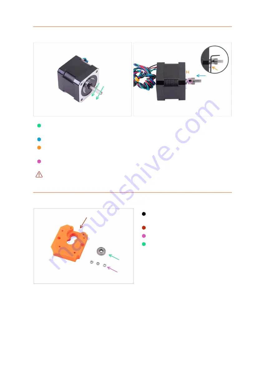
STEP 33
Assembling the Extruder motor
There is a flat part on the motor shaft. Rotate it similarly to the first picture. See the
direction of the arrows.
Place the Extruder pinion on the Extruder motor shaft as shown in the picture.
Don't press the pinion against the motor. Leave a 1.5 millimeters gap between both
parts. You can use the 1.5mm Allen key to set the gap.
The set screw must be facing directly against the pad (flat part) on the shaft.
Slightly tighten the screw.
Ensure you have the correct orientation of the pulley on the shaft.
It can be placed
both ways, but only one is correct.
STEP 34
Extruder-front: parts preparation
For the following steps, please
prepare:
MINI-Extruder-front (1x)
M3n nut (3x)
Bearing 625 2Z (1x)
Содержание Original Prusa MINI
Страница 5: ...Original Prusa MINI kit assembly 5 1 Introduction ...
Страница 14: ...14 Original Prusa MINI kit assembly 2 YZ axis assembly ...
Страница 47: ...Original Prusa MINI kit assembly 47 3 X axis Extruder assembly ...
Страница 73: ...Original Prusa MINI kit assembly 73 4 Print head Heatbed assembly ...
Страница 87: ...Original Prusa MINI kit assembly 87 5 LCD assembly Electronics ...
Страница 100: ...100 Original Prusa MINI kit assembly 6 Spool holder assembly ...
Страница 105: ...Original Prusa MINI kit assembly 105 7 Preflight check ...
Страница 109: ...109 Notes ...
Страница 110: ...110 ...
Страница 111: ...111 Notes ...
Страница 112: ...112 ...
Страница 113: ...113 Notes ...
Страница 114: ...114 ...
Страница 115: ...115 Notes ...
Страница 116: ...116 ...


