5
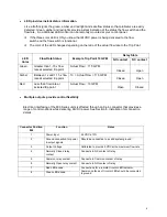
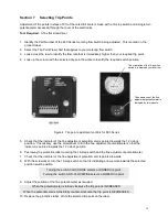
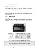
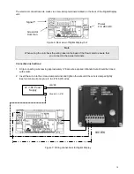
Trip points are selected by adjusting a 16-position switch as shown in Table 1.
This feature provides the ability to change trip point settings predictably, accurately and reproducibly
without the use of complex instrumentation.
See Section 7 for instructions on selecting trip points.
•
Optional potentiometer provides fine tuning capability
If your trip point must be set with finer control than is provided by the 16-position switch a
potentiometer provides the adjustment you need. This potentiometer can be adjusted from 7 o’clock
t
o 5 o’clock positions. Refer to Section 7 for instructions on selecting trip points.
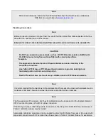
Note
Elbows and other devices that induce swirling motion in the flowing liquid that are installed
within a distance of approximately 10 x the ID of the inlet port reduce the linear velocity
of liquid through the flow sensor.
When such devices are present the actual flow rate through the flow sensor may be HIGHER
than is suggested in Table 1.
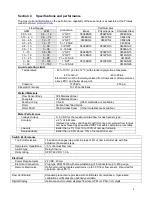
Model
Number
Switch Position
0
1
2
3
4
5
6
7
8
9
A
B
C
D
E
F
0804BN03
0804PN03
0804SN03
0.01
0.03
0.05
0.06
0.08
0.10
0.12
0.14
0.16
0.17
0.19
0.21
0.23
0.25
0.26
0.28
0804BN2
0804PN2
0804SN2
0806SA2
0.18
0.29
0.41
0.52
0.63
0.75
0.86
0.98
1.09
1.20
1.32
1.43
1.54
1.66
1.77
1.89
0804BN4
0804PN4
0804SN4
0806SA4
0.36
0.62
0.87
1.13
1.39
1.65
1.91
2.17
2.43
2.69
2.95
3.21
3.46
3.72
3.98
4.24
0806BN10
0806PN10
0806SN10
0808SA10
0.89
1.46
2.03
2.60
3.17
3.74
4.31
4.88
5.45
6.02
6.58
7.15
7.22
8.29
8.86
9.43
0808BN15
0808PN15
0808SN15
1.6
2.5
3.3
4.1
5.0
5.8
6.6
7.5
8.3
9.1
10.0
10.9
11.7
12.5
13.3
14.2
0812BN19
0812PN19
0812SN19
0812SA19
1.6
2.7
3.8
4.8
5.9
7.0
8.1
9.2
10.3
11.4
12.5
13.5
14.6
15.7
16.8
17.9
0812SA25
1.8
3.2
4.7
6.1
7.6
9.0
10.5 12.0 13.4 14.9
16.3 17.8 19.2 20.7
22.1 23.6
0816BN50
0816PN50
0816SN50
0816SA50
3.6
6.5
9.4
12.3
15.2
18.1
21.0
23.9
26.8
29.7
32.6
35.5
38.4
41.3
44.2
47.1
Table 1: Flow Rate in GPM at selected Switch Positions with straight connection to inlet
port and fine adjustment potentiometer in the 12 o’clock position.

