19
Cleaning the 800 Series Flow Sensor
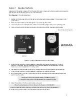
9. Position the faceplate so that the holes
in the faceplate are aligned with the screw
holes in the front of the flow sensor body.
Replace the 6 securing screws.
Tighten the screws to a torque of 40 in-lbs
(hand tighten with a normal screwdriver).
11. Install the flow meter in your system.
Turn on liquid flow and check for leaks at the faceplate and connecting ports.
Tighten all connections as required to eliminate leaks.
Section 11 Calibration & Recalibration
Note
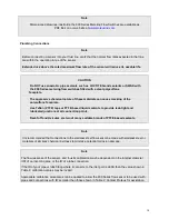
800 Series sensors are calibrated at Proteus with water at temperatures ranging
from 22 to 28C.
Changes in fluid type can alter the calibrated response of the sensor.
Large changes in liquid temperature can alter the calibrated response of the sensor.
Please contact Proteus Technical Support if a specialized calibration is needed.
Note
As described in the Plumbing Connections section on page 10, the response of the 800
Series flow sensor may be affected by the way in which the sensor is connected to your
system.
The 800 Series metering flow switch has been calibrated during manufacture to provide
an output of 5.0 VDC for the full scale limit of the flow meter, with straight pipe
connections.
Customized calibration procedures can be performed to change the flow rate corresponding
to 5.0 VDC, for fluids other than water and with connections with internal diameters less than
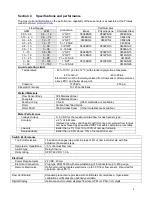
those used in the flow sensors. (See Table 2, page 10).
Recalibration
The calibration of the 800 metering flow switch should be checked at 12-month intervals, and recalibrated
as required. Re-calibration may be accomplished in either of two ways:


