background image


10 

Note 


Dimensioned drawings illustrating the 800 Series Metering Flow Switches are available as 

 PDF files on our web site at 

www.proteusind.com

. 


Plumbing Connections 


Note 

 
Before connecting a sensor into your fluid line, verify that the normal flow rates expected in that line 
are within the operating range of the sensor.  
 

Extended use above the rated maximum flow rate of the sensor will reduce its useable life. 


CAUTION 


Do NOT use anaerobic pipe sealants such as LOCTITE brand sealants or SWAK with 


the 800 Series metering flow switches fitted with a clear polysulfone 

         faceplate. 
 

The aggressive chemical nature of these materials can cause cracking of the  


polysulfone faceplate. 


Use Teflon (PTFE) tape or PTFE-based liquid sealants to provide leak-tight and 


lubricated junctions at all connection points. 


Real-Tuff and Hercules are two of many suitable brands of PTFE-based sealants.  


Note 


It is recommended that connections to the stainless steel flow sensor be made with stainless steel or 
materials of similarly chemical inertness to minimize potential corrosion damage. 


Note 

 
The flow response of the sensor, and thus its calibration may be dependent on the internal diameter 
(ID) of an incoming pipe, or the ID of a tube connection. 
 
If the ID of your pipe or tube fitting where it connects to the inlet port is LESS than the value shown in 
Table 2, calibration values may be invalid. 
 
Appropriate calibration procedures can be applied to allow the 800 Series flow sensor to be used with 
pipes and connections with ID’s smaller than those shown in Table 2. Contact Proteus for assistance. 
 

Содержание 0804BN03

Страница 1: ...800 Series Metering Flow Switches TECHNICAL REFERENCE MANUAL...

Страница 2: ...2 3 How the flow sensor works 7 4 Specifications and performance 8 5 Product certifications 9 6 Installation 9 Mechanical 9 Electrical 13 7 Selecting Trip Points 14 8 Measuring Flow Rate 16 9 Digital...

Страница 3: ...ince 1978 Section 2 Features and Functions Flow ranges from 0 05 to 50 GPM 0 2 to 190 LPM Eight flow ranges are provided in the 800 Series in brass polypropylene or stainless steel NPT and SAE connect...

Страница 4: ...ely retrofittable in place of existing Proteus flow switches The distance between the 800 Series pipe or fitting connections is identical to those of previous Proteus flow sensors Stainless Steel face...

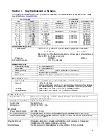
Страница 5: ...nsor may be HIGHER than is suggested in Table 1 Model Number Switch Position 0 1 2 3 4 5 6 7 8 9 A B C D E F 0804BN03 0804PN03 0804SN03 0 01 0 03 0 05 0 06 0 08 0 10 0 12 0 14 0 16 0 17 0 19 0 21 0 23...

Страница 6: ...x flow rate at selected trip point 10 Actual Flow 11 5 GPM Closed Open Red Less than flow rate at selected trip point Actual Flow 10 GPM Open Closed Multiple outputs provide control flexibility Elect...

Страница 7: ...oltage is continuously compared to a user selected trip point voltage When the measured voltage is above the trip point the built in relay remains in its active state If the measured voltage falls bel...

Страница 8: ...tainless Steel Sealing O ring Viton Other materials are available Rotor Carbon fiber filled Nylon Rotor Shaft 316 Stainless Steel Other materials are available Meter Performance Voltage Output 0 5 VDC...

Страница 9: ...ing or tubing is used the 800 Series metering flow switch may be supported by direct connection to the pipe or tubing Panel mounting To mount the sensor behind a panel two of the faceplate securing sc...

Страница 10: ...PTFE tape or PTFE based liquid sealants to provide leak tight and lubricated junctions at all connection points Real Tuff and Hercules are two of many suitable brands of PTFE based sealants Note It is...

Страница 11: ...more than 10 x pipe ID be used between the flow sensor and any up stream devices to minimize these effects Appropriate calibration procedures must be used to provide an accurate flow measurement with...

Страница 12: ...ontact with the face of the port using a wrench 2 Check to be certain that the O ring fits easily into the non threaded receiving area of the port and is not pinched Adjustable fittings 1 Ensure that...

Страница 13: ...ith the electrical circuit and control functions of the system in which the sensor is to be included should perform installation of this product Electrical inputs and outputs are provided at a single...

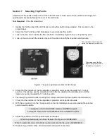
Страница 14: ...necessary use the screwdriver to turn the fine adjustment potentiometer so that the indicator is pointed towards the 12 o clock position 6 Peel away the protective label covering the 16 step switch a...

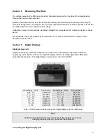
Страница 15: ...flow Section 9 Digital Displays Digital display units Digital panel display meters are available to provide a direct local display of flow rate in selected engineering units Each unit has a 3 digit LC...

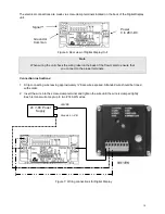
Страница 16: ...you connect to the proper terminals Connection instructions 1 Strip connecting wire leaving approximately bare wire exposed Stranded wire should be tinned with solder 2 Insert the wire into the screw...

Страница 17: ...ugh the flow meter In most cases annual cleaning immediately prior to recalibration is sufficient Tools required Wrenches to disconnect the flow meter from your flow circuit A flat screw driver Soft c...

Страница 18: ...surface of the rotor If the bearing surface is worn or not round replace the rotor Inspect the stainless steel shaft If the shaft shows signs of scoring or other wear replace the shaft or the whole fa...

Страница 19: ...er the calibrated response of the sensor Please contact Proteus Technical Support if a specialized calibration is needed Note As described in the Plumbing Connections section on page 10 the response o...

Страница 20: ...bel will be attached to the flow meter Direct calibration against NIST traceable standards is optionally available Calibration by another laboratory The calibrating laboratory will issue certificates...

Отзывы: