14
Section 7
Selecting Trip Points
Adjustment of trip points in steps of 6% of the rated full scale is made with a 16-step switch and a single turn
potentiometer accessed through the cover of the electronics.
Tool Required
: A fine flat screwdriver
1. Identify the Part Number of the 800 Series metering flow switch being adjusted. This is noted on the
product label.
2. Select the Trip Point Flow chart that applies to your metering flow switch.
3. Look across the row to identify the flow rate that is immediately higher than your required trip point.
4. Look up the column with the selected trip point flow rate to identify the required switch position.
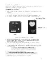
Figure 4: Trip point adjustment controls for 800 Series
5.
Check that the indicator of the fine adjustment potentiometer is pointed towards the 12 o’clock
position. If necessary, use the screwdriver to turn the fine adjustment potentiometer so that the
indicator is pointed towards the 12 o’clock position
6. Peel away the protective label covering the 16-step switch and the fine adjustment potentiometer.
7. Check that the indicator of the fine adjustment potentiometer is pointed towards
8. With the screwdriver, turn the 16-step switch so that its indicating arrow points towards the selected
position switch position.
Turning the switch CLOCKWISE selects a HIGHER trip point.
Turning the switch ANTI-CLOCKWISE selects a LOWER trip point.
9. Adjust the position of the fine potentiometer as required.
When the potentiometer is turned clockwise the trip point is INCREASED.
When the potentiometer is turned fully counter-clockwise the trip point is DECREASED.
10. Replace the protective label. Write the selected trip point on the label.
The orientation of the 16-position
switch is indicated by small arrow.
The orientation of the fine
adjustment potentiometer is
indicated by two indents.


