16
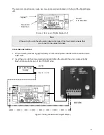
The electrical connections are made via screw-clamp terminals located on the back of the Digital Display
unit.
Figure 6: Rear view of Digital Display Unit
Note
When wiring the unit check the wiring label on the back of the flow meter to ensure that
you connect to the proper terminals.
Connection instructions:
1.
Strip connecting wire leaving approximately ¼” bare wire exposed. Stranded wire should be tinned
with solder.
2. Insert the wire into the screw-clamp terminal and tighten the wire until the wire is clamped tightly.
Each terminal will accept up to two #14 AWG wires.
24 V-DC Power
Supply
Signal
+
Ground or
Common
Power
9 to 28V-DC
+24VDC
C
Ground or
-ve
Figure 7: Wiring connections for Digital Display


