Pro-face PS-4600 Series Скачать руководство пользователя страница 97

PS-4600 Series User Manual

97

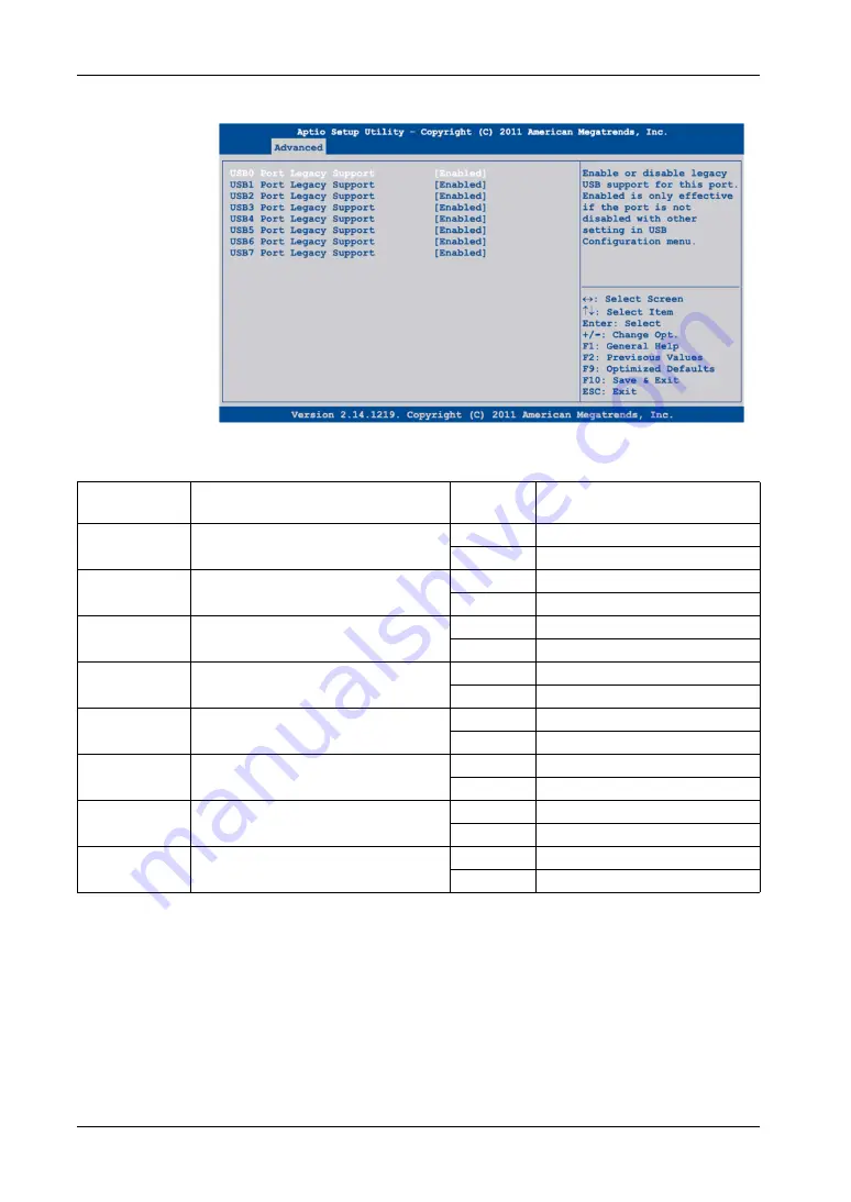
Advanced Per Port Legacy USB Support Control

The table shows the 

Per Port Legacy USB Support Control

 options:

BIOS Setting

Description

Setting Op-
tions

Effect

USB0 Port Lega-
cy Support

Option to enable/disable legacy support for 
the USB4 port.

Disabled

Disables the USB port.

Enabled

Enables the USB port.

USB1 Port Lega-
cy Support

Option to enable/disable legacy support for 
the USB2 port.

Disabled

Disables the USB port.

Enabled

Enables the USB port.

USB2 Port Lega-
cy Support

Option to enable/disable legacy support for 
the USB3 port.

Disabled

Disables the USB port.

Enabled

Enables the USB port.

USB3 Port Lega-
cy Support

Option to enable/disable legacy support for 
the USB1 port.

Disabled

Disables the USB port.

Enabled

Enables the USB port.

USB4 Port Lega-
cy Support

Option to enable/disable USB port legacy 
support on the bus unit.

Disabled

Disables the USB port.

Enabled

Enables the USB port.

USB5 Port Lega-
cy Support

Option to enable/disable USB port legacy 
support on the monitor/panel interface.

Disabled

Disables the USB port.

Enabled

Enables the USB port.

USB6 Port Lega-
cy Support

Option to enable/disable USB port legacy 
support for the USB5 port.

Disabled

Disables the USB port.

Enabled

Enables the USB port.

USB7 Port Lega-
cy Support

Option to enable/disable USB port legacy 
support on the monitor/panel option.

Disabled

Disables the USB port.

Enabled

Enables the USB port.

Содержание PS-4600 Series

Страница 1: ......

Страница 2: ...improvements or amendments or have found errors in this publication please notify us No part of this document may be reproduced in any form or by any means electronic or mechanical including photocop...

Страница 3: ...Characteristics 36 Industrial Personal Computer Interface Characteristics 41 Environmental Characteristics 42 Chapter 4 Dimensions Assembly 43 Industrial Personal Computer Dimensions 44 Installation...

Страница 4: ...Installation 144 8 5 Slide in Disk Drive and Fan Kit 151 Slide in Disk Drive Description and Installation 152 Fan Kit Installation and Removing 156 8 6 Main Memory Cards and CFast Cards 158 CFast Card...

Страница 5: ...ates that an electrical hazard exists which will result in personal injury if the instructions are not followed This is the safety alert symbol It is used to alert you to potential personal injury haz...

Страница 6: ...sonnel No responsibility is assumed by Pro face for any consequences arising out of the use of this material A qualified person is one who has skills and knowledge related to the construction and oper...

Страница 7: ...Standard Model P Rear Mount Model F Product Generation Reserved Display 12 XGA 6 Expansion Slots 0 slot 0 1 slot 1 PCI 1 1 slot 1 PCIe C 2 slots 1 PCI 1 PCIe 2 2 slots 2 PCI A CPU Type Celeron 827E D...

Страница 8: ...16 GB J Primary CFast 4 GB Secondary CFast 4 GB for Windows Embedded Standard 2009 MUI L Primary CFast 8 GB Secondary CFast 4 GB for Windows Embedded Standard 7 Premium MUI 32 bit M HDD 500 GB P SSD 6...

Страница 9: ...vementioned trade names and trademarks Related Documents You can download these technical publications and other technical information from our website Otasuke Pro at http www pro face com otasuke Glo...

Страница 10: ...the Industrial Personal Computer and the power supply Always use a properly rated voltage sensing device to confirm power is off Replace and secure all covers or elements of the system before applying...

Страница 11: ...stem Installed hardware Installed software WARNING UNINTENDED EQUIPMENT OPERATION Use only Pro face software with the devices described in this manual Failure to follow these instructions can result i...

Страница 12: ...About the Book 12...

Страница 13: ...2013 General Overview Subject of this Part This part provides an overview of the Industrial Personal Computer products What Is in This Part This part contains the following chapters Chapter Chapter N...

Страница 14: ...General Overview 14...

Страница 15: ...fic aspects related to the operation of the Industrial Personal Computer What Is in This Chapter This chapter contains the following topics Topic Page Federal Communications Commission Radio Frequency...

Страница 16: ...diate sufficient electromagnetic energy to cause interference in nearby devices Install and test the Industrial Personal Computer to ensure that the electromagnetic energy generated by nearby devices...

Страница 17: ...lified personnel may include at the application design level engineering department personnel who are familiar with automation safety concepts for example a design engineer at the equipment implementa...

Страница 18: ...tions and standards such as certified models and certificates see the following or product markings http www pro face com worldwide html Compliance Standards Pro face tested this product for complianc...

Страница 19: ...c boards It must be disposed of in specific treatment channels The product contains cells and or storage batteries which must be collected and processed separately when they have run out and at the en...

Страница 20: ...bed in this manual comply with the European Directives concerning Electromagnetic Compatibility and Low Voltage CE marking when used as specified in the relevant documentation in applications for whic...

Страница 21: ...labeling NOTE Some Industrial Personal Computer devices are not yet rated as suitable for use in hazardous locations Always use your product in conformance with the product labeling and this manual D...

Страница 22: ...has been switched off or the area is known to be non hazardous This applies to all connections including power ground serial parallel network and rear USB connections Never use unshielded ungrounded c...

Страница 23: ...dous locations These switches are available from a wide number of sources It is the responsibility to ensure you select a power switch that conforms to the hazardous location rating for the installati...

Страница 24: ...intained Always secure the D Sub connectors to the workstation mating connectors via the two screws located on both sides DANGER POTENTIAL FOR EXPLOSION Always confirm the ANSI ISA 12 12 01 and CSA C2...

Страница 25: ...ndustrial Personal Computer in a hazardous location Wire the equipment in accordance with the National Electrical Code article 501 10 B for Class I Division 2 hazardous locations Install the Industria...

Страница 26: ...Important Information 26...

Страница 27: ...l Overview Subject of this Chapter This chapter provides a physical overview of the Industrial Personal Computer What Is in This Chapter This chapter contains the following topics Topic Page Package C...

Страница 28: ...ial Personal Computer confirm that all items listed here are present Industrial Personal Computer 1 Installation Fasteners 10 per set only for Standard Models Restore DVD ROM containing the software r...

Страница 29: ...carefully packed with special attention to quality However should you find anything damaged or missing contact your local distributor immediately DC Terminal Block For the DC Industrial Personal Comp...

Страница 30: ...USB cover must be tighten with 0 55 0 05Nm 4 87 0 44 lb in to comply with degree of protection NEMA 4x Indoor and IP65 WARNING RISK OF BURNS Do not touch the surface of the heat sink during operation...

Страница 31: ...atus LEDs 2 Power Reset buttons 3 Slide in Disk 4 Main memory cards 5 CFast slot NOTICE UNINTENDED EQUIPMENT OPERATION Do not use the front USB while the machine is in operation Always keep the cover...

Страница 32: ...1000 MBit 5 USB3 6 USB4 7 DVI I 8 MIC Line IN Line out 9 COM2 10 COM1 11 Add on interface module slot 2 IF2 12 Add on interface module slot 1 IF1 13 Ground connection 14 DC power connector Bottom View...

Страница 33: ...uter 1 Power LED 2 HDD LED 3 Link LED 4 RUN LED 5 POWER button 6 RESET button NOTE Modifying products to install an HDD into a Slide in Disk when it was not installed from factory requires to change t...

Страница 34: ...not reset the processor LED Color State Meaning Power Green On Supply voltage is OK Flashing The device has booted the battery status is low The data buffering is provided for approximately 500 hours...

Страница 35: ...13 Characteristics Subject of this Chapter This chapter lists the product characteristics What Is in This Chapter This chapter contains the following topics Topic Page Industrial Personal Computer Cha...

Страница 36: ...ation with HDD storage device into Slide in Disk SDRAM 2 x DDR3 25 6 GB s 16 GB max Graphics Controller Intel HD Graphics 3000 Video Mem ory Up to 1 GB reserved from main memory Color depth 32 bit max...

Страница 37: ...device into Slide in Disk SDRAM 2 x DDR3 25 6 GB s 16 GB max Graphics Controller Intel HD Graphics 4000 Video Mem ory Up to1 GB reserved from main memory Color depth 32 bit maximum RGB Reso lution 350...

Страница 38: ...stive film resolution 4 096 x 4 096 Backlight LED Life span 50 000 h 25 C 77 F WARNING UNINTENDED EQUIPMENT OPERATION Do not touch simultaneously more than two point on the Industrial Personal Compute...

Страница 39: ...ages for Multi language see page 40 2 For Windows Embedded Standard 2009 CFast of 4 GB or more is required For Win dows Embedded Standard 7 Premium CFast of 8 GB or more is required Element Characteri...

Страница 40: ...bedded Standard 2009 Windows Embedded Standard 7 Arabic 1 Bulgarian 1 Chinese Simplified 1 Chinese Traditional 1 Croatian 1 Czech 1 Danish 1 Dutch 1 English Estonian 1 Finnish 1 French German Greek 1...

Страница 41: ...on this product ETH1 ETH2 Internal port number Windows 7 LAN1 LAN2 Internal port number Windows XP LAN2 LAN1 Element Characteristics Amount 2 Type RS 232C modem capable not electrically isolated UART...

Страница 42: ...ltitude 2000 m 6560 ft max EN IEC 61131 2 Vibration EN IEC 60068 2 6 Fc Operation continuous for prod ucts with SSD or CFast card stor age device 2 9 Hz 1 5 mm 9 200 Hz 4 9 m s2 5 8 4 Hz 1 75 mm 8 4 1...

Страница 43: ...ions Assembly Subject of this Chapter This chapter describes Industrial Personal Computer dimensions and installation panels What Is in This Chapter This chapter contains the following topics Topic Pa...

Страница 44: ...he figure shows the dimensions of the Industrial Personal Computer 12 NOTE Measurement A depends on the number of slot PCI PCIe cards see page 45 DVD RW 247 9 72 3 5 0 14 313 12 32 33 1 30 239 9 41 18...

Страница 45: ...al Personal Computer 59 5 mm 2 342 in 1 slot Industrial Personal Computer 114 2 mm 4 496 in 2 slots Industrial Personal Computer 134 5 mm 5 295 in Nominal Measurement General Tolerance acc DIN ISO 276...

Страница 46: ...CI PCIe cards see page 47 DVD RW 6 4x 1x45 5 2x 1x45 146 5 75 292 11 50 246 Touch Panel active area 9 69 184 5 Touch Panel active area 7 26 184 32 LCD active area 7 26 245 76 LCD active area 9 68 100...

Страница 47: ...rial Personal Computer 67 mm 2 637 in 1 slot Industrial Personal Computer 121 7 mm 4 791 in 2 slots Industrial Personal Computer 142 mm 5 591 in Nominal Measurement General Tolerance acc DIN ISO 2768...

Страница 48: ...eft and right sides 50 mm 1 96 in or more on the rear side and 100 mm 3 93 in or more above and below the product from all adjacent structures and equipment Install the Industrial Personal Computer wi...

Страница 49: ...e spacing on the top bottom and sides is as follows Mounting Orientation The figures show the allowable mounting orientation for the Industrial Personal Computer depending on the Slide in Slot 1 optio...

Страница 50: ...below Standard Models 1 Installation panel A 301 5 1 0 mm 11 87 0 04 0 in B 227 5 1 0 mm 8 96 0 04 0 in C 1 6 9 mm 0 06 0 35 in Rear Mount Models 137 5 0 5 0 132 5 0 5 0 5 41 0 02 0 1 5 0 06 Center of...

Страница 51: ...ls of vibration are expected and the installation panel can move Attach metal reinforcing strips to the inside of the panel near the panel cut out to increase the strength of the installation panel En...

Страница 52: ...nit are not exceeded Ensure that the installation panel opening and thickness are within the specified tolerances Before mounting the Industrial Personal Computer into a cabinet or panel ensure that t...

Страница 53: ...mputer NOTE When checking the gasket avoid contact with the sharp edges of the Industrial Personal Computer frame and insert it completely into its groove 2 Check whether the included mounting screws...

Страница 54: ...l Personal Computer frame and insert it completely into its groove 2 Insert the Industrial Personal Computer into the back of the smooth flat installation panel opening see page 50 3 From the front fa...

Страница 55: ...04 2013 Implementation Subject of this Part This part describes setting up the product What Is in This Part This part contains the following chapters Chapter Chapter Name Page 5 Getting Started 57 6 I...

Страница 56: ...Implementation 56...

Страница 57: ...pment time by eliminating the need for custom drivers or conversion efforts WES7 also provides many tools for the customization of menus boot screens and dialog boxes With WES7 you can remove the Wind...

Страница 58: ...the corresponding Right click function is activated for instance menu will display Calibrating a Touch Screen If the touch position recognized in the panel deviates from the actual touch you need to...

Страница 59: ...pter This chapter describes the connection of the Industrial Personal Computer to the main power supply It also describes the USB ports and identifies the serial interface pin assignment What Is in Th...

Страница 60: ...n Dedicated Ground Connect the Industrial Personal Computer ground to a dedicated ground Wire Cross section Maximum Line Length 2 5 mm2 AWG 13 30 m 98 ft 60 m 196 ft round trip WARNING UNINTENDED EQUI...

Страница 61: ...round through other devices using shared ground terminals Shared Ground Avoid Ground Loop When connecting an external device to a Industrial Personal Computer with the shield ground SG ensure that a g...

Страница 62: ...When grounding follow the procedure below Step Action 1 Check that the grounding resistance is 100 or less 2 When connecting the SG line to another device ensure that the design of the system connect...

Страница 63: ...wn to be non hazardous This applies to all connections including power ground serial parallel network and rear USB connections Never use unshielded ungrounded cables in hazardous locations When enclos...

Страница 64: ...power is off Replace and secure all covers or elements of the system before applying power to the unit Use only the specified voltage when operating the Industrial Personal Computer The AC unit is de...

Страница 65: ...puter and confirm that the DC power supply has been disconnected from its power source 2 Remove the terminal block from the power connector and connect the power cord to the terminal block as shown be...

Страница 66: ...Replace and secure all covers or elements of the system before applying power to the unit Use only the specified voltage when operating the Industrial Personal Computer The AC unit is designed to use...

Страница 67: ...d connect the power cord to the AC terminal block as shown below Use 75 C 167 F wire Use wire with cross section 0 75 mm2 to 2 5 mm2 AWG 18 to AWG 12 Attach the wire ends with screws Use a slot screwd...

Страница 68: ...nnect equipment unless power has been switched off or the area is known to be non hazardous This applies to all connections including power ground serial parallel network and rear USB connections Neve...

Страница 69: ...ed values of Voc or Uo and Isc or Io for the associated apparatus are less than or equal to Vmax Ui and Imax Ii for the non incendive apparatus and the approved values of Ca Co and La Lo for the assoc...

Страница 70: ...at a different electrical potential than the panel even if both are connected to ground The Industrial Personal Computer serial port is not isolated The SG signal ground and the functional ground FG t...

Страница 71: ...2 RXD 3 TXD 4 DTR 5 GND 6 DSR 7 RTS 8 CTS 9 RI CAUTION LOSS OF POWER Ensure that communication connections do not place excessive stress on the communication ports of the Industrial Personal Computer...

Страница 72: ...Industrial Personal Computer Connections 72...

Страница 73: ...ation of the BIOS EIO0000001596 04 2013 Configuration of the BIOS What Is in This Chapter This chapter contains the following topics Topic Page BIOS Options 74 Main Menu 77 Advanced Menu PCI and PCIe...

Страница 74: ...ge appears if the CMOS data contains anomalies but you can continue the boot procedure by pressing the F1 key To prevent the message from appearing at each restart open the BIOS setup by pressing the...

Страница 75: ...ontroller has been initialized F11 Displays the boot menu Lists all bootable devices that are connected to the system Use the up cursor and down cursor and then press the Enter key to select the boot...

Страница 76: ...s to the next item Changes the value of the selected item Enter Changes to the selected menu PgUp Changes to the previous page PgDn Changes to the next page Start Jumps to the first BIOS menu item or...

Страница 77: ...ate the BIOS was created None Platform Informa tion Displays information about the chipset CPU board and main memory Enter Opens the Platform information sub menu System Date This is the current syste...

Страница 78: ...Configuration of the BIOS 78 Platform Information The figure shows the Main submenu...

Страница 79: ...OS version Memory RC Version Displays the memory RC version Total memory Displays the total memory Memory frequency Displays the memory frequency PCH information Name Displays the platform controller...

Страница 80: ...gs Configuration of start time from being switched off Enter Open submenu CPU Configuration Configures the CPU settings Enter Opens submenu Chipset Configuration Configuration of chipset settings Ente...

Страница 81: ...s the value in PCI ticks VGA Palette Snoop Option to support graphics cards with 256 colors This option should set only to En able if colors are not displayed correctly Disabled Disables this function...

Страница 82: ...em IRQ3 IRQ4 IRQ5 IRQ6 IRQ10 IRQ11 IRQ14 IRQ15 Manual assignment PIRQB Option for setting the PIRQ B Auto Automatic assignment by the BIOS and operating system IRQ3 IRQ4 IRQ5 IRQ6 IRQ10 IRQ11 IRQ14 IR...

Страница 83: ...5 IRQ6 IRQ10 IRQ11 IRQ14 IRQ15 Manual assignment PIRQH Option for setting the PIRQ H Auto Automatic assignment by the BIOS and operating system IRQ3 IRQ4 IRQ5 IRQ6 IRQ10 IRQ11 IRQ14 IRQ15 Manual assig...

Страница 84: ...Root Port 0 Configuration of the PCI Express settings on Port 0 Enter Opens the submenu PCI Express Root Port 1 Configuration of the PCI Express settings on port 1 Enter Opens the submenu PCI Express...

Страница 85: ...to Automatic mapping of packet size 128 4096 bytes Manual mapping of packet size Maximum Read Request Option to set the maximum read re quest Auto Automatic assignment 128 4096 bytes Manual assignment...

Страница 86: ...ns Effect Completion Tim eout In device functions that support a program mable completion timeout the software permits modifying the completion timeout value Default The timeout range is between 50 s...

Страница 87: ...function Enabled Enables this function Target Link Speed If supported by hardware and set to force to 2 5 GT s for downstream ports this sets an upper limit on link operational speed by re districting...

Страница 88: ...elect the root port configuration on the 16 PCIe channels of the PEG port 1 x 16 Configuration with 1 x 16 2 x 8 Configuration with 2 x 8 1 x 8 2 x 4 Configuration with 1 x 8 and 2 x 4 PEG0 Displays t...

Страница 89: ...to the PEG1 port is operated None PEG1 speed Option for setting the maximum transfer rate for the PEG1 port Auto The maximum transfer rate is select ed Gen1 The maximum transfer rate is 2 5 GT s Gen2...

Страница 90: ...saving func tion Power consumption is lower than with L0 but the exit latency higher ASPM L0sL1 Automatic assignment of L0s or L1 power saving function by the PCIe device ASPM L0s4 Option for setting...

Страница 91: ...root port 1 enabled Disabled PCI Express root port 1 and 2 are dis abled ASPM Active State Power Management Option for setting a power saving function L0s L1 for PCIE devices if not required full pow...

Страница 92: ...Option for generating a system error de tected if a fatal error detected is registered by a device on the root port or on the root port itself Enabled Enables this function Disabled Disables this fun...

Страница 93: ...rved I O range 4K 8K 12K 16K 20K for this root bridge 4 20 BIOS Setting Description Setting Op tions Effect BIOS Setting Description Setting Op tions Effect EHCI1 Ports 0 5 Sets USB EHCI Controller 1...

Страница 94: ...and operated with maximum USB 2 0 Enabled Port 1 is routed to xHCI The corresponding SS port is en abled HS Port Number 2 Switchable Option to switch HS port 2 between xHCI and EHCI Disabled Port 2 is...

Страница 95: ...g sys tems without a fully automated EHCI func tion Disabled Disables this function With op erating systems that do not have a fully automated EHCI function USB devices are only operated with USB 1 1...

Страница 96: ...isables the USB port Enabled Enables the USB port USB Port num ber 3 Option to enable disable the USB1 port Disabled Disables the USB port Enabled Enables the USB port USB Port num ber 4 Option to ena...

Страница 97: ...Enables the USB port USB3 Port Lega cy Support Option to enable disable legacy support for the USB1 port Disabled Disables the USB port Enabled Enables the USB port USB4 Port Lega cy Support Option t...

Страница 98: ...Boot Priority Selection Submenu BIOS Setting Description Setting Options Effect Boot Device Pri ority Configuration of boot order Enter Opens the submenu Boot Device Priority see page 99 Boot Configur...

Страница 99: ...change the sequence of items in the device list You can add to the list device types that are not connected 1st Boot Device Use this option to de fine the boot drive Disabled SATA 0 Drive SATA 1 Driv...

Страница 100: ...The setup activation key is shown for x seconds Yes The setup menu is displayed Enable Popup Boot Menu Option to enable disable the popup boot menu Yes Enables this function Press F11 during POST to s...

Страница 101: ...Options Effect Administrator Pass word Function to enter change the administrator pass word Enter Enter password BIOS Setting Description Setting Options Effect Primary Slave HDD User Password With a...

Страница 102: ...rd Disk Security Master Passwords BIOS Setting Description Setting Options Effect Primary Slave HDD Master Password With a valid user password you can change or configure hard drives without rebooting...

Страница 103: ...aving the changes modem Yes No Save Changes and Reset BIOS setup is closed with this item Changes made are saved in CMOS after confirmation and the system is reboot ed Yes No Save changes and reset BI...

Страница 104: ...Configuration of the BIOS 104 The switch positions at delivery represents the optimum BIOS default values and should not be changed...

Страница 105: ...l as commercial devices and boards with this product NOTE The Slide in Disk drive can only be exchanged without removing the Industrial Personal Computer Unit from the control cabinet if the wall is l...

Страница 106: ...ailure to follow these instructions will result in death or serious injury DANGER POTENTIAL FOR EXPLOSION Always confirm the ANSI ISA 12 12 01 and CSA C22 2 N 213 hazardous location rating of your dev...

Страница 107: ...al Personal Computer chassis Failure to follow these instructions can result in injury or equipment damage CAUTION STATIC SENSITIVE COMPONENTS Industrial Personal Computer internal components includin...

Страница 108: ...describes the AC Power Supply Module the UPS Battery Unit and the UPS principle What Is in This Section This section contains the following topics Topic Page AC Power Supply Unit Description and Insta...

Страница 109: ...Unit can optionally be mounted on the Industrial Personal Computer to allow the Industrial Personal Computer to be operated with 100 240 Vac The figure shows a Industrial Personal Computer equipped wi...

Страница 110: ...rent Max 5 5 A EN 60529 Protection IP20 protection back as fully assembled and oper ational device Ambient Temperature Operation Storage and Transport 0 55 C 32 131 F 20 60 C 4 140 F Relative Humidity...

Страница 111: ...ore applying power to the unit Use only the specified voltage when operating the Industrial Personal Computer The AC unit is designed to use 100 240 Vac input The DC unit is designed to use 24 Vdc Alw...

Страница 112: ...ersonal Computer Be sure that the housing is parallel and the plug on the AC Power Supply Unit is insert ed in the socket on the Industrial Personal Computer There must not be any pres sure or mechani...

Страница 113: ...ardware or cables Unplug the power cable from both the Industrial Personal Computer and the power supply Always use a properly rated voltage sensing device to confirm power is off Replace and secure a...

Страница 114: ...ORQUE AND LOOSE HARDWARE Do not exert more than 0 5 Nm 4 5 lb in of torque when tightening the installation fastener enclosure accessory or terminal block screws Tightening the screws with excessive f...

Страница 115: ...main features of the UPS option are Long lasting maintenance free rechargeable batteries Communication via integrated interfaces Temperature sensor Deep discharge protection NOTE The UPS Interface Boa...

Страница 116: ...n immediately without interruption This means that all running programs are ended properly by the UPS software This prevents the possibility of inconsistent data NOTE This function is only available i...

Страница 117: ...s Single cell X cell Rated Voltage 24 Vdc Operating Current Max 4 5 Ah Battery Charging Current Max 2 88 A Ambient Temperature Charging Mode Storage and Transport 30 60 C 22 140 F 65 80 C 85 176 F Rel...

Страница 118: ...Hardware Modifications 118 The figure shows the dimensions of the UPS battery unit...

Страница 119: ...ning torque 0 4 0 5 Nm 3 54 4 42 lbf in Wire Cross Section Temperature Sensor Wire Voltage Wire 2 x 0 5 mm2 AWG 20 2 x 2 5 mm2 AWG 13 Line Resistance at 20 C 0 5 mm2 2 5 mm2 Max 39 km 63 mile Max 7 98...

Страница 120: ...ated voltage sensing device to confirm power is off Replace and secure all covers or elements of the system before applying power to the unit Use only the specified voltage when operating the Industri...

Страница 121: ...clamp terminal block 6 Tighten the connected wires in the screw clamps with a screwdriver to a max tight ening torque of 0 4 Nm 7 Connect the 4 pin screw clamp to the UPS Interface Board and tighten t...

Страница 122: ...Hardware Modifications 122 Drilling Template of UPS Battery Unit For mounting the UPS Battery Unit use the following figure as the drilling template...

Страница 123: ...iew This section describes the 3 interface modules and of the installation What Is in This Section This section contains the following topics Topic Page Interface Module Installation 124 COM Expansion...

Страница 124: ...ardware or cables Unplug the power cable from both the Industrial Personal Computer and the power supply Always use a properly rated voltage sensing device to confirm power is off Replace and secure a...

Страница 125: ...as identified in the table below After replacing or installing an interface module restore BIOS default settings via Exit Menu see page 103 The table provides the possible positions of the interface...

Страница 126: ...r cover Failure to follow these instructions can result in equipment damage Step Action 1 Disconnect the power cord to the Industrial Personal Computer 2 Touch the housing or ground connection not the...

Страница 127: ...t to the Industrial Personal Computer with 2 Torx screws T10 NOTE The recommended torque to tighten these screws is 0 5 Nm 4 5 lb in 8 Replace the cover plate Secure the cover plate to the Industrial...

Страница 128: ...llation fastener enclosure accessory or terminal block screws Tightening the screws with excessive force can damage the plastic installation fastener When installing or removing screws ensure that the...

Страница 129: ...electrical connection The serial interface and COM Expansion Board use a different pin assignment for RS 232C communication When using the COM Expansion Board for RS 232C communication pins 1 4 6 and...

Страница 130: ...422 Cable cross section RS485 Wire insulation Conductor resistance Stranding Shield 4 x 0 16 mm 26 AWG tinned Cu wire 4 x 0 25 mm 24 AWG tinned Cu wire 4 x 0 25 mm 24 AWG tinned Cu wire PE 82 Ohm km W...

Страница 131: ...o greater potential differences between bus stations which can hinder communication You can improve the communication by running a ground wire with the other wires Pin Assignment RS232 RS422 485 1 N C...

Страница 132: ...grated in the Industrial Personal Computer The UPS Interface Board is installed using the materials included in the delivery For more information regarding installation see Interface module installati...

Страница 133: ...nstallation of the slot expansion It describes the Slide in Slot the Slide in Disk drive and the PCI PCIE cards What Is in This Section This section contains the following topics Topic Page Slot Expan...

Страница 134: ...ter and the power supply Always use a properly rated voltage sensing device to confirm power is off Replace and secure all covers or elements of the system before applying power to the unit Use only t...

Страница 135: ...ch the housing or ground connection not the power supply to discharge any electrostatic charge from your body 3 Remove the Industrial Personal Computer from the control cabinet and follow the steps in...

Страница 136: ...s 136 6 Mount the slot expansion on the rear side of the Industrial Personal Computer using the Torx screws T20 included in the delivery NOTE The recommended torque to tighten these screws is 1 2 Nm 1...

Страница 137: ...llation see page 52 CAUTION OVERTORQUE AND LOOSE HARDWARE Do not exert more than 0 5 Nm 4 5 lb in of torque when tightening the installation fastener enclosure accessory or terminal block screws Tight...

Страница 138: ...Computer and the power supply Always use a properly rated voltage sensing device to confirm power is off Replace and secure all covers or elements of the system before applying power to the unit Use...

Страница 139: ...the power supply to discharge any electrostatic charge from your body 3 Remove the Industrial Personal Computer from the control cabinet and follow the steps inIndustrial Personal Computer Installatio...

Страница 140: ...y pressing in the 6 marked snap arms and removing the slot cover 7 Install the Slide in Slot in the slot expansion Be sure to insert the Slide in Slot in the black guide rails at the top and bottom of...

Страница 141: ...ON OVERTORQUE AND LOOSE HARDWARE Do not exert more than 0 5 Nm 4 5 lb in of torque when tightening the installation fastener enclosure accessory or terminal block screws Tightening the screws with exc...

Страница 142: ...n Disk drives can be installed The following figure shows the Slide in Disk drives 1 Hard disk 2 Slide in Disk Adapter Unit 3 Slide in Slot Adapter Unit 1 Slide in Slot Adapter Unit 2 Slide in Disk Ad...

Страница 143: ...4600 Series User Manual 143 The following figure shows the Slide in Disk Adapter Unit DVD Multi Drive The DVD Multi Drive can be used with a Slide in Slot The following figure shows the DVD Multi Dri...

Страница 144: ...irm power is off Replace and secure all covers or elements of the system before applying power to the unit Use only the specified voltage when operating the Industrial Personal Computer The AC unit is...

Страница 145: ...ype you can use standard PCI 2 2 half size cards or PCI Express PCIe half size cards NOTE PCI PCIe cards cannot exceed the following dimensions The figure shows the dimensions of the standard half siz...

Страница 146: ...ion PCI PCIe Card Installation NOTE Be sure to remove all power before attempting this procedure Industrial Personal Com puter Quantity PCI 32 bit half size 2 2 33 MHz PCIe Half size 1 0 a x8 2 GB s B...

Страница 147: ...the housing or ground connection not the power supply to discharge any electrostatic charge from your body 3 Remove the Industrial Personal Computer from the control cabinet and follow the steps in In...

Страница 148: ...Hardware Modifications 148 5 Remove the PCI slot cover from the slot expansion Remove the marked Torx screws T10 and the slot cover Step Action...

Страница 149: ...ard in the slot expansion Be sure to insert the PCI PCIe card in the black guide rail in the top of the slot expansion Fasten the PCI PCIe card using the marked previously removed Torx screws T10 1 Gu...

Страница 150: ...of torque when tightening the installation fastener enclosure accessory or terminal block screws Tightening the screws with excessive force can damage the plastic installation fastener When installing...

Страница 151: ...Kit Overview This section describes the installation of the Slide in Disk drive and fan kit What Is in This Section This section contains the following topics Topic Page Slide in Disk Drive Descripti...

Страница 152: ...ccessories hardware or cables Unplug the power cable from both the Industrial Personal Computer and the power supply Always use a properly rated voltage sensing device to confirm power is off Replace...

Страница 153: ...es how to install a Slide in Disk drive NOTICE ELECTROSTATIC DISCHARGE Take the necessary protective measures against electrostatic discharge before attempting to remove the Industrial Personal Comput...

Страница 154: ...emove the Slide in Disk drive 9 When inserting a Slide in Disk drive be sure to align it with the guide rails Tuck the removal strip back between the drive and the frame as it was before you pulled it...

Страница 155: ...tallation fastener enclosure accessory or terminal block screws Tightening the screws with excessive force can damage the plastic installation fastener When installing or removing screws ensure that t...

Страница 156: ...device before removing any covers or elements of the system and prior to installing or removing any accessories hardware or cables Unplug the power cable from both the Industrial Personal Computer and...

Страница 157: ...ress it in until it latches Make sure the fan kit is inserted so that the connections match up Step Action Step Action 1 Disconnect the power supply to the Industrial Personal Computer 2 Touch the hou...

Страница 158: ...Cards Overview This section describes the installation of the main memory and CFast cards What Is in This Section This section contains the following topics Topic Page CFast Card Installation and Rem...

Страница 159: ...confirm power is off Replace and secure all covers or elements of the system before applying power to the unit Use only the specified voltage when operating the Industrial Personal Computer The AC un...

Страница 160: ...n Windows in an orderly fashion and remove all power from the de vice 2 Open the CFast card cover 3 Insert the CFast card firmly into the CFast card slot and check that the eject but ton pops out 4 Cl...

Страница 161: ...two RAM cards of different sizes for example 2 GB and 4 GB are inserted If two 2 GB cards or one 4 GB card is installed on a 32 bit operating system only 3 GB of main memory can be used On a 64 bit op...

Страница 162: ...power supply Always use a properly rated voltage sensing device to confirm power is off Replace and secure all covers or elements of the system before applying power to the unit Use only the specified...

Страница 163: ...uter from the control cabinet and follow the steps in Industrial Personal Computer Installation see page 52 in reverse order 4 Place the Industrial Personal Computer on a clean and flat surface 5 Remo...

Страница 164: ...rder 10 The Industrial Personal Computer can now be mounted back in the control cab inet see Industrial Personal Computer Installation see page 52 CAUTION OVERTORQUE AND LOOSE HARDWARE Do not exert mo...

Страница 165: ...allows data to be distributed across multiple hard drives to provide data redundancy or to enhance data storage performance The latest version of Intel Rapid Storage Technology can also be downloaded...

Страница 166: ...BIOS setup You can access the following screens from the BIOS setup CREATE VOLUME MENU DELETE VOLUME MENU RESET RAID DATA RECOVERY VOLUME OPTIONS Key Function Up cursor Go to previous item Down curso...

Страница 167: ...ther Master or Recovery Master Recovery Defines the hard disks as Master or Recovery Strip Size2 Option for configuring the size of data blocks 4 kB 8 kB 16 kB 32 kB 64 kB 128 kB Configures the size o...

Страница 168: ...to be deleted must be selected and then deleted by pressing DEL NOTE This option deletes all data on the drive including the operating system Reset Disks to Non RAID You can delete an existing RAID v...

Страница 169: ...nd master disk by using the RECOVERY VOLUME OPTIONS Configuration for SATA RAID Option When installation is complete a Intel Rapid Storage Technology icon is available in the task bar Double click the...

Страница 170: ...Hardware Modifications 170...

Страница 171: ...nal Computer 12 Installation EIO0000001596 04 2013 Installation Subject of this Part This part describes the product installation What Is in This Part This part contains the following chapters Chapter...

Страница 172: ...Installation 172...

Страница 173: ...or EIO0000001596 04 2013 System Monitor Subject of this Chapter This chapter describes the system monitor features of the Industrial Personal Computer What Is in This Chapter This chapter contains the...

Страница 174: ...an alarm occurs Accessing the System Monitor The procedure below shows how to access the System Monitor interface System Monitor Interface Description The System Monitor interface shows all possible...

Страница 175: ...ystem Monitor to the system tray 4 Resets alarmed item 5 Disable buzzer and sound Only active when sound or buzzer is playing The following table describes the icons of the system parameter tab Icon S...

Страница 176: ...temperature parameters Fan Status NOTE Only available with the fan kit option and an HDD into Slide in Disk slot The following figure shows the Fan tab The following table describes the status messag...

Страница 177: ...me value in percent with a bar graph is displayed otherwise Not supported is shown The following table describes the status message of the Industrial Personal Computer drives Status Meaning Pass No al...

Страница 178: ...displayed Status Meaning Pass No alarm detected Error Battery unit detected a failure for example battery is disconnect ed On Battery Power failure system is running on battery Low Battery Battery lev...

Страница 179: ...eset 2 Closes the System Monitor Alert window 3 Shows the main window 4 If the check box is selected closes the window for one hour even though the alarm is active A new alarm shows the window again 5...

Страница 180: ...meter has its own tab Use the following dialog box tabs to display the monitoring parameters and set up the various elements to monitor Temperature System Monitor Properties The screenshot below shows...

Страница 181: ...D into Slide in Disk slot The screenshot below shows the Fan tab SMART System Monitor Properties The screenshot below shows the SMART tab Field Description Monitor the function of the PC fans Select t...

Страница 182: ...unit UPS CMOS Select this check box to enable and begin monitoring the installed battery unit When enabled see page 182 set the Error action Field Description Turn on buzzer Select this check box to e...

Страница 183: ...tenance EIO0000001596 04 2013 Maintenance Subject of this Chapter This chapter covers maintenance of the Industrial Personal Computer What Is in This Chapter This chapter contains the following topics...

Страница 184: ...t leads with skin or clothing Before Reinstallation Hardware required Reinstallation DVD ROM External DVD drive compatible with DVD R DL format or a USB connection for Industrial Personal Computer wit...

Страница 185: ...ified voltage when operating the Industrial Personal Computer The AC unit is designed to use 100 240 Vac input The DC unit is designed to use 24 Vdc Always check whether your device is AC or DC powere...

Страница 186: ...Maintenance 186 WARNING RISK OF BURNS Do not touch the surface of the heat sink during operation Failure to follow these instructions can result in death serious injury or equipment damage...

Страница 187: ...ial of the screen Failure to follow these instructions can result in injury or equipment damage Step Action 1 Disconnect the power supply to the Industrial Personal Computer 2 Touch the housing or gro...

Страница 188: ...ty 950 mAh Voltage 3 Vdc Self Discharge at 23 C 73 4 F 1 per year Storage Time Maximum 3 years at 30 C 86 F Environmental Characteristics Storage Temperature 20 60 C 4 140 F Relative Humidity 0 95 non...

Страница 189: ...t of the Industrial Personal Computer and remove the battery 4 The battery should not be held by its edges Insulated tweezers may also be used for inserting the battery 5 Insert the new battery with c...

Страница 190: ...r than with the type specified in this document may present a risk of fire or explosion WARNING IMPROPER BATTERY CAN PROVOKE FIRE OR EXPLOSION Replace battery only with identical type Type CR2477N Fai...

Страница 191: ...User Manual Magelis Industrial Personal Computer 12 EIO0000001596 04 2013 Appendices What Is in This Part This part contains the following chapters Chapter Chapter Name Page A Accessories 193 B After...

Страница 192: ...192...

Страница 193: ...lide in Slot PFXZPSSSAD2 Adaptor to install a CFast card to Slide in Disk PFXZPSSCAD2 COM Expansion Board Add 1 ch for RS 232C 422 485 PFXZPSIUCMR42 UPS Interface Board PFXZPSIUUPM2 UPS battery unit P...

Страница 194: ...Accessories 194 Replacement FAN kit for PS 4600 PFXZPPIUFAN2 Replacement FAN filter for PS 4600 5 pcs PFXZPPFTFAN2 Description Reference...

Страница 195: ...User Manual B Magelis Industrial Personal Computer 12 Accessories EIO0000001596 04 2013 After sales service For details on after sales service refer to Pro face website at http www pro face com trans...

Страница 196: ...After sales service 196...

Отзывы: